


 English
 русский
 Español
 عربى
عربى 简体中文
简体中文100MSY/100MSY With Sub-Spindle Y-Axis CNC Lathe Slant Bed Supplier

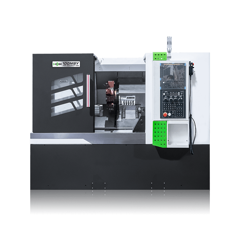
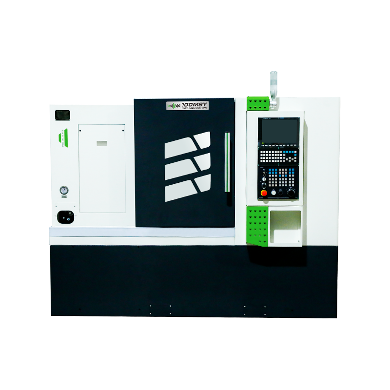
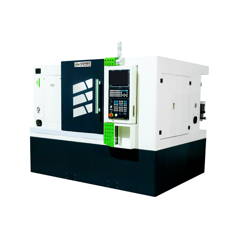
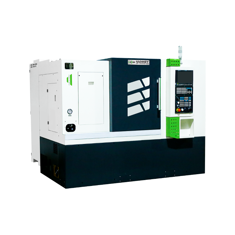
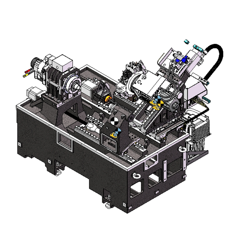
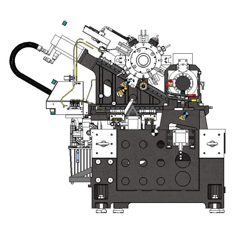
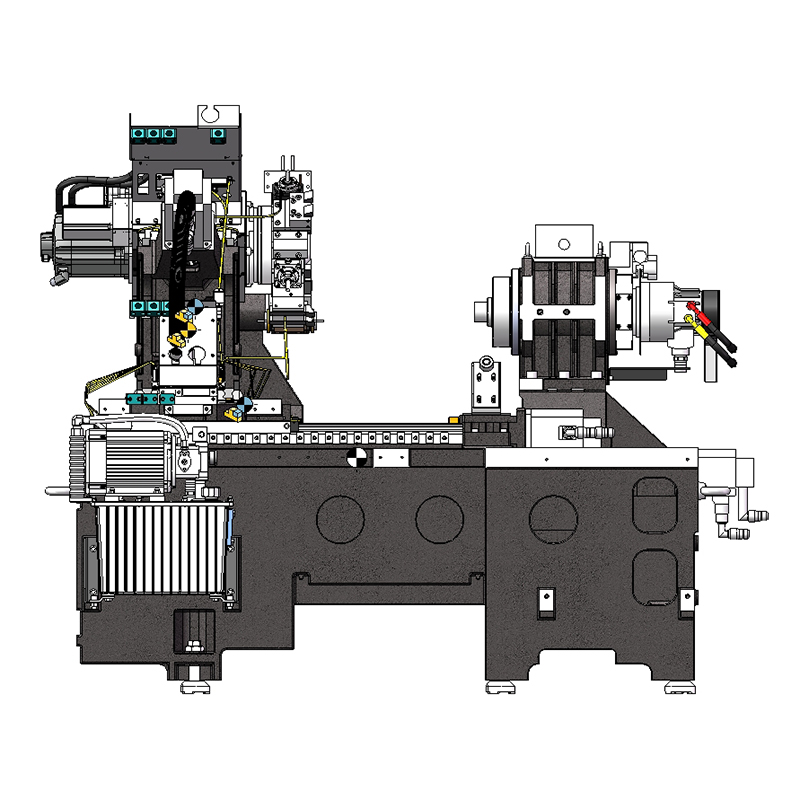
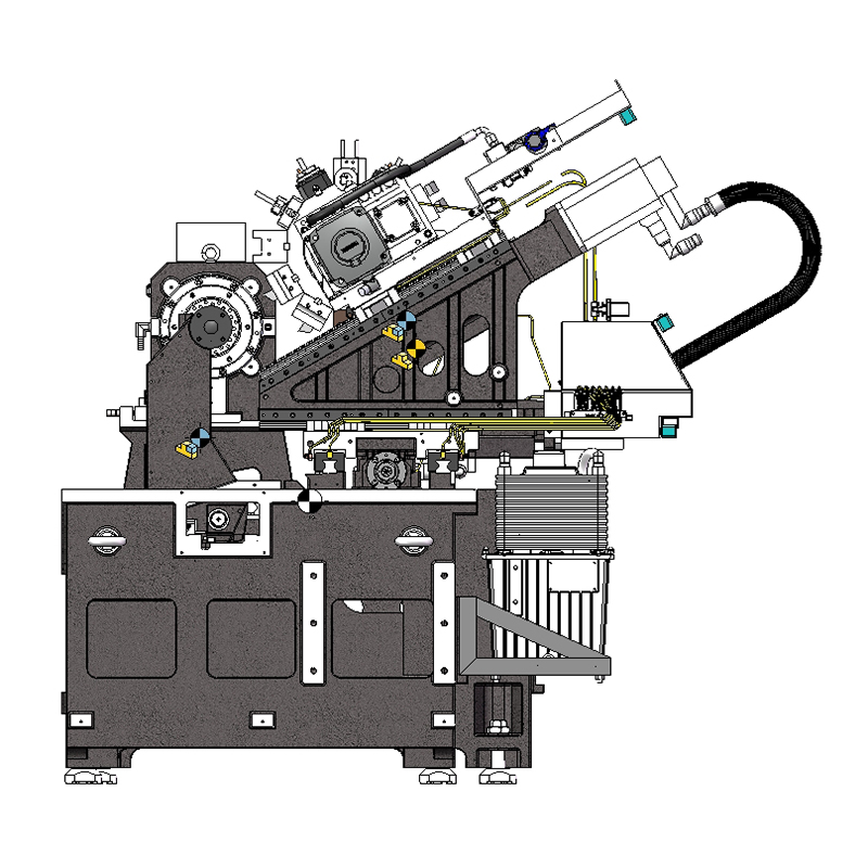
100MSY/100MSY With Sub-Spindle Y-Axis CNC Lathe Slant Bed
100MSY/100MSY With Sub-Spindle CNC Lathe Slant Bed With Y-Axis can automatically complete the cutting of internal and external cylindrical surfaces, conical surfaces, arc surfaces, end faces, grooving, chamfering and other processes for various shaft and disk parts, and can turn metric straight threads, end face threads and inch straight threads. Various turning processes such as taper threads.
|
|
Maximum Machining Diameter: 260mm |
|
|
Maximum Machining Length: 350mm |
|
|
Chuck Size: 6" inch |


-
DETAIL PARAMETERS
-
VIDEO DISPLAY
100MSY CNC Lathe Slant Bed Introduction
1. The high-rigidity Y-axis is realized through the movement of the middle(inclined) and large (horizontal) slides, which involves continuous two-laxis interpolation. This enables milling operations with maximum rigidity.
2. The roller linear guideway meets the requirements of high speed and high efficiency, reduces frictional resistance and deformation due to temperature rise, improves the machining precision, and ensures the long-term stability of cutting machining precision.
3. X/Z-axis servo motors are directly connected to the precision ball screw through flexible couplings, and the screws are fixed at both ends. The rigidity of mounting base is improved to minimize the screw deformation caused by frequent, high-speed positioning or heavy cutting.. A pair of 60° angular contact precision bearings are used for high speed and precision.
4. The programmable tailstock is equipped with overload protection and is driven by a servo motor for movement and clamping. This significantly improves machining efficiency.
Description of the basic structural features of the Lathe machine tool
1, Bed
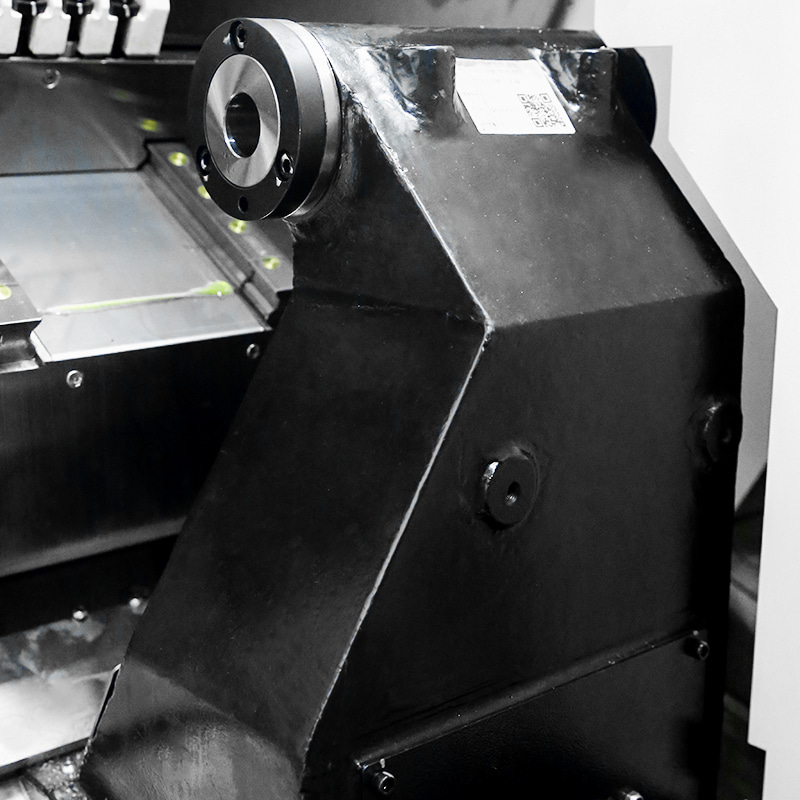
The bed adopts an integrated high-low rail bed design, with a thick-walled, multi-ribbed, multi-cavity structure to ensure heavy cutting capabilities. The bed is cast with high-quality resin sand, with good rigidity, good shock resistance, and smooth chip removal.
2, Spindle box
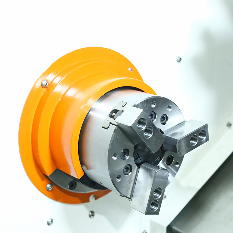
The spindle bearings use high-quality, high-precision bearings and a servo synchronous electric spindle, which provides high torque and stable output. The spindle box bearings use double-row cylindrical roller bearings and double-direction thrust angular contact bearings, which provide high rigidity. The heat dissipation adopts a structural design that reduces the thermal deformation of the spindle, enabling the spindle to maintain the relative stability of the spindle axis during long-term operation.
3, Feed system
The X , Y and Z axis servo motors are directly connected to the precision ball screw through elastic couplings, with high precision. The two ends of the screw are fixed, which improves the support stiffness of the support seat, minimizes the distortion of the screw caused by frequent high-speed positioning and heavy cutting, and the bearings use 60-degree angular contact pairs of precision bearings for screws, with high speed and high precision.
4, Slide
The transmission adopts imported linear rolling guides from Taiwan to meet the requirements of high speed and high efficiency, reduce friction resistance and temperature rise deformation, improve processing accuracy, and ensure the long-term stability of cutting processing accuracy.
5, Turret
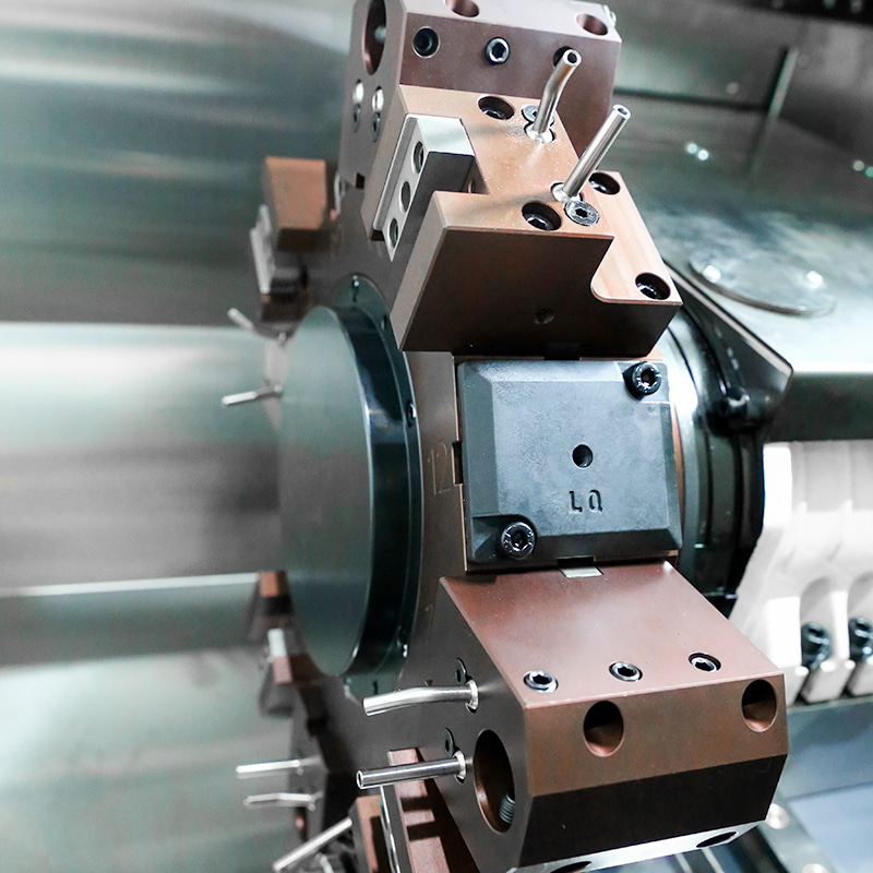
The high-rigidity hydraulic servo turret is adopted. Through the servo system optimization compensation, it cooperates with the servo spindle to realize multi-axis linkage, which can complete spindle positioning, rigid tapping, curved surface milling and other functions, greatly enriching the functions of the machine tool, improving the adaptability of the machine tool, and meeting the processing needs of various parts.
6, Hydraulic system
In addition to program control, the clamping, loosening and telescopic extension of the hydraulic chuck and the tailstock sleeve can be controlled by foot, which is convenient and fast. Hydraulic pressure adjustment adopts panel-type rotary operation, dial display, safe and convenient adjustment.
7, Lubrication device
The machine tool adopts an automatic centralized lubrication system, with timed and quantitative oil supply. The oil distributor adjusts the oil supply pressure according to the pressure requirements of different lubrication parts to ensure that any lubrication parts (such as guide rails, inserts, screws, nuts and other friction pairs) can be fully lubricated, and the lubrication system alarm function is set.
8, Cooling system
The inclined bed CNC lathe adopts full guide rail protection, and the cooling box and chip conveyor are separated from the main machine to ensure that the machine tool accuracy is not affected by thermal cutting.
9, Electrical system
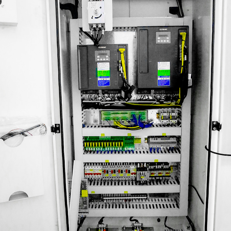
The machine tool electrical unit cabinet has good sealing performance and is equipped with an electrical cabinet air conditioner to ensure that the CNC system of the machine tool works normally under high temperature and high humidity environment.
10, Extreme anti-collision measures
The bearing seats at the extreme travel positions of the positive and negative directions of the axis are equipped with rubber buffer anti-collision devices to provide the final protection for the double nut ball screw pair from loss collision under abnormal conditions.
11, Safety protection
Fully protected inner sheet metal design and fully enclosed outer sheet metal design. The machine tool does not deform or vibrate when working. The inner protection guide rail, screw rod, nut and bearing are made of stainless steel telescopic cover. It is convenient to remove chips and clean machine chips.
Main Parts of Slant Bed Lathe
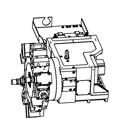 |
Integrated Driven Tool TurretThe driven tool turret is characterized by high positioning accuracy, a compact design, and fast. It enables tool changes without lifting, thereby boosting machining efficiency. |
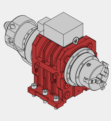
Built-In SpindleThe spindle is driven by a high-torque, high-efficiency, and high-performance permanent magnet synchronous motor. Additionally, P4 double-row short cylindrical roller bearings are adopted. This setup ensures the spindle's high precision, rigidity, and stability. Spindle Speed: 5000rpm Spindle Power: 12.3 kW Spindle Taper Hole: Φ56 mm |
 |
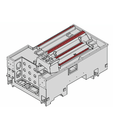 |
Guideway of the BedThe bed guideway adopts 35-type roller linear guideway and 6 sliders to maintain the rigidity, accuracy and stability of the machine tool during heavy cutting. The automated loading and unloading unit (optional) is integrated with the machine, significantly reducing the floor space. x/Y/Z-axis Travel: 125/±40/360mm x/Y/Z-axis Rapid Traverse Speed: 25/10/25 m/min |
CNC Lathe Slant Bed 100MSY Feature
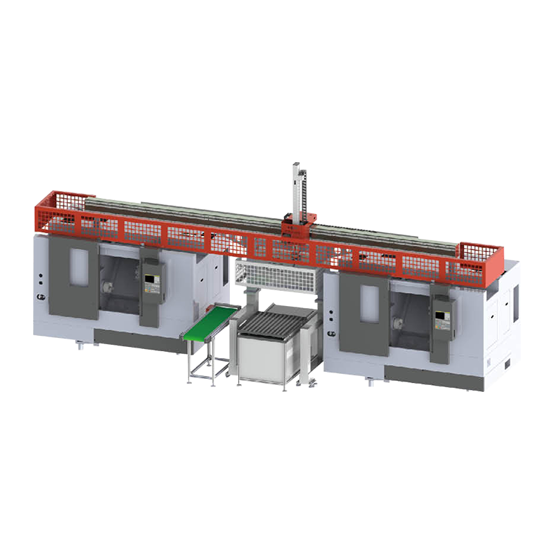
Adopts 30°Machine Bed, High Rigidity Simulative Y-Axis with 12 Post Driven Tool Turret BMT45, with Built-in Spindle(max spindle speed 5000rpm),Hydraulic Through Chuck, and Servo Programmable Tailstock,Small Land Occupation, Extremly Shorten the Working Time for Short Shaft and Plate Workpiece Processing.
|
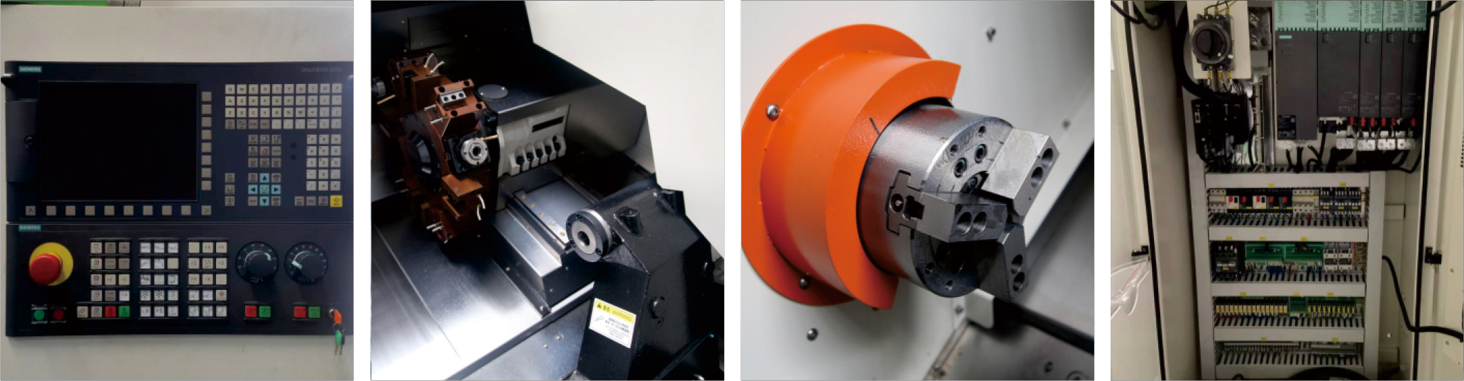
Standard |
Optional |
|
1. SIEMENS 828D Basic Control System |
1. FANUC 0i-TF Plus Control System |
|
2. A2-5 |
2. GSK 988TA Absolute Control System |
|
3. Built-in Spindle |
3. SYNTEC 22TB Control System |
|
4. Hydraulic Through Chuck 6inch |
4. RENEISHAW Auto Tool Setter |
|
5. 12 Post Driven Tool Turret (BMT55) |
5. Auto Bar Feeder |
|
6. Servo Programmable Tailstock |
6. Oil Skimmer |
|
7. Roller Linear Guideway |
7. Chip Conveyor |
100MSY CNC Lathe Slant Bed Specification
| Configuration | 100MSY | 100MSY With Sub-Spindle | ||
| Machining Capacity | Maximum Swing Over Bed | φ/mm | 500 | 500 |
| Maximum Swing Over Slide | φ/mm | 260 | 260 | |
| Maximum Machining Length | mm | 350 | 350 | |
| Maximum Diameter of Bar | φ/mm | 45 | 45 | |
| Maximum Machining Diameter | φ/mm | 260 | 260 | |
| Built-in Spindle | Spindle Head Type | GB59001 | A2-5 | A2-5,with Sub-Spindle A2-4 |
| Spindle Taper Hole | φ/mm | 56 | 56, with Sub-Spindle 36 | |
| Spindle Speed Range | r/min | 50-5000 | 50-5000, with Sub-Spindle 50-6000 | |
| Spindle Power | kW | 12.3 | 12.3, with Sub-Spindle 9.5 | |
| Spindle Output Torque | N·m | 110 | 110, with Sub-Spindle 24.3 | |
| Chuck Type | Hydraulic Through Chuck | Hydraulic Through Chuck | ||
| Chuck Siz | inch | 6" | 6", with Sub-Spindle Chuck 5" | |
| Feed Rate | Rapid Traverse Speed On X-axis | m/min | 25 | 25 |
| Rapid Traverse Speed On Y-axis | m/min | 10 | 10 | |
| Rapid Traverse Speed On Z-axis | m/min | 25 | 25 | |
| Servo Motor Torque On X-axis | N·m | 8.9 | 8.9 | |
| Servo Motor Torque On Y-axis | N·m | 8.9 | 8.9 | |
| Servo Motor Torque On Z-axis | N·m | 8.9 | 8.9 | |
| Sub-Spindle Servo Motor Torque | N·m | —— | 10 | |
| Servo Motor Torque On Z1-axis | N·m | 4.7 | —— | |
| X-axis Travel | mm | 130 | 130 | |
| Y-axis Travel | mm | ±40 | 土40 | |
| Z-axis Travel | mm | 360 | 360 | |
| Sub-Spindle Travel | mm | 400 | ||
| Guideway Type | Roller Linear Guideway | Roller Linear Guideway | ||
| Turret | Turret Type | 12Post Driven Tool Turret(BMT45) | 12Post Driven Tool Turret(BMT45) | |
| Tool Size | mm | 20×20/φ25/ER25 | 20×20/φ25/ER25 | |
| Tailstock | Tailstock Type | Servo Programmable | ||
| Tailstock Travel | mm | 390 | ||
| Tailstock Sleeve Diameter | φ/mm | 65 | ||
| Internal Taper of Tailstock Sleeve | MT4 | |||
| Power Source | Total Rated Power | KVA | 22 | 33 |
| Total Rated Current | A | 48 | 65 | |
| Dimension | Machine Weight | kg | 3000 | 3100 |
| Machine Dimension | L*W*H(mm) | 2190×1780×1800 | 2190×1780×1800 | |
Please note that there may be slight differences in appearance and parameter depending on your options.
Tool Interferogram

100MSY CNC Lathe Slant Bed Application
Frequently Asked Questions
Q1: Who is the 100MSY designed for and what problems does it solve?
The 100MSY Sub-Spindle Y-Axis CNC Slant Bed Lathe is designed for manufacturers producing small-to-medium diameter complex parts that require complete machining — including turning, milling, drilling, tapping, and off-centre operations on both ends — in a single machine cycle. It solves the productivity and accuracy problems created by multi-machine routing: eliminating manual part transfers, re-fixturing errors, inter-machine queue times, and the cost of operating separate lathes and machining centres for parts that can be fully completed on the 100MSY in one uninterrupted cycle.
Q2: What does the 'MSY' designation mean in the 100MSY model name?
MSY in the 100MSY model designation indicates three core machine capabilities beyond standard CNC turning: M stands for milling — the machine is equipped with live tooling for powered rotating tool operations; S stands for sub-spindle — a synchronized second spindle enables automatic part hand-off and complete machining of both workpiece ends; and Y refers to the Y-axis — a lateral linear axis perpendicular to X and Z that enables true off-centre milling and complex multi-plane feature generation that C-axis live tooling alone cannot achieve.
Q3: What size workpieces does the 100MSY handle?
The 100MSY is optimised for small-to-medium diameter workpieces consistent with its model designation. It is particularly well suited to small precision parts produced from bar stock — connectors, medical components, instrument parts, small automotive components, hydraulic cartridge valves, and precision fastener components — where the combination of small diameter, high complexity, and tight tolerances makes the MSY configuration significantly more efficient than traditional multi-machine routing.
Q4: How does the Y-axis on the 100MSY differ from standard C-axis live tooling?
C-axis live tooling on a standard turning centre allows the spindle to be indexed and locked at precise angular positions, while rotating live tools perform milling, drilling, and tapping operations. However, all these operations are centred on the spindle axis — any feature must pass through or be concentric with the centreline. The Y-axis on the 100MSY adds a perpendicular offset, physically moving the tool away from the centreline to machine truly eccentric features: off-centre bores, lateral flats, offset keyways, and complex pocket geometries positioned anywhere across the workpiece face.
Q5: What CNC control manages the 100MSY's multi-axis operations?
The 100MSY uses a multi-channel CNC control — typically FANUC 0i-TF with dual-path and Y-axis capability or Siemens 840D sl — to simultaneously manage the main spindle with C-axis, the sub-spindle with C-axis, the Y-axis, and the live tooling turret. The control handles spindle synchronization for part transfer, balanced cutting routines that machine both spindles concurrently, and Y-axis milling cycles that combine with C-axis rotation to machine complex 3D features on small precision components.
Q6: Can the 100MSY be integrated with a bar feeder for lights-out production?
Yes. The 100MSY is well-suited to bar-fed unmanned production. A short or long bar feeder connected to the main spindle enables continuous automatic production of complete parts from bar stock — the machine feeds, turns the first end, mills and drills, hands the part to the sub-spindle, completes the reverse side, and ejects the finished part into a parts catcher or conveyor, all without operator involvement between cycles. For high-volume small precision part production, this capability is transformative for cost per part and shift utilization.
Q7: What industries most commonly use the 100MSY?
The 100MSY is most commonly used in the medical device industry for small implant components, bone screws, and surgical instrument parts; the automotive industry for small precision shafts, pins, and valve components; the electronics and connector industry for precision contact housings and terminal bodies; the hydraulic industry for cartridge valve components and small bore fittings; and high-mix precision job shops that produce a wide variety of complex small parts in medium production volumes.
Q8: What are the key specifications to evaluate when purchasing a 100MSY?
Critical specifications to review when purchasing the 100MSY include: maximum turning diameter and bar capacity, Y-axis travel range (which determines the maximum off-centre offset achievable), live tooling RPM and power, sub-spindle chuck size and gripping range, maximum distance between main and sub-spindle face positions, control system multi-channel capability, and whether the machine is configured for bar feeder interface. Evaluating these parameters against your most complex part family requirements ensures the machine is correctly specified before purchase.

KEEP IN TOUCH
About Us
Taizhou Eastern CNC Technology Co., Ltd.
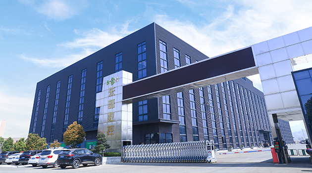
We are a well-known brand and professional wholesale 100MSY/100MSY With Sub-Spindle Y-Axis CNC Lathe Slant Bed in China. It is committed to providing professional machine tools and production application solutions to global users, and actively provides customization. It has more than 650 employees. With different models and more than 40 derivative products, we strive to achieve the vision goal of "building a famous brand in the machine tool equipment manufacturing industry".
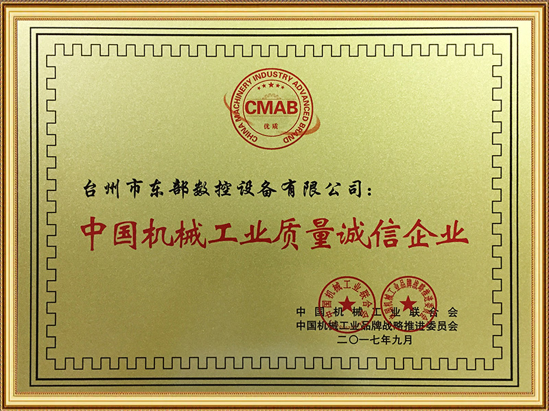
Certificate Of Honor




News
-
Overview In the metal-cutting industry, the "machine bed" is a component often overlooked by buyers, yet it is the decisive factor in whether a lathe can operate with long-term stability. While the v...
READ MORE -
Introduction In the past two years, many small and medium-sized machine shops have faced a common set of challenges: difficulty in recruiting skilled labor, shrinking batch sizes, and increasingly co...
READ MORE -
Overview Talk to anyone who's actually run a metalworking lathe for a living, and one thing comes up again and again: get the machine wrong, and every step after that gets harder. A shaft that's only...
READ MORE -
Abstract Double-turret CNC lathes and dual-spindle CNC lathes are two machine tool configurations frequently discussed together in the field of precision parts manufacturing. While both aim to boost ...
READ MORE -
Abstract As the demand for precision manufacturing continues to evolve, Y-axis lathes are increasingly becoming a focal point for manufacturing enterprises. Compared to traditional CNC lathes, Y-axis...
READ MORE
How to buy CNC machine tools
-
01
Contact Us
All of your quotes will be answered within 2 hours by our professional sales support.
-
02
Get A Free Quote
Use reliable parts and components to ensure product quality.
-
03
Fast Delivery
You can expect your order fulfilled within 60 days after placing the order.
-
04
After-sale Support
All our products come with a one-year warranty.

-

-

sales@east-cnc.com
-

Shangma Industry Area, Shitang Town, Wenling City, Taizhou, Zhejiang, China.
-

Products
Message
Copyright © Taizhou Eastern CNC Technology Co., Ltd.

Machine Tool Manufacturer Privacy Policy