350M/350M-L/350MS/350MS With Sub-Spindle Slant Lathe for Long Shaft Turning and Milling Supplier
 Home / Products / CNC Slant Bed Lathe / 350M/350M-L/350MS/350MS With Sub-Spindle Slant Lathe for Long Shaft Turning and Milling
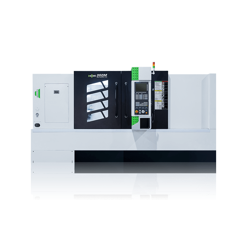
350M/350M-L/350MS/350MS With Sub-Spindle Slant Lathe for Long Shaft Turning and Milling
350M/350M-L/350MS/350MS With Sub-Spindle CNC Slant Bed Lathe For Long Shaft Turning And Milling
|
|
Maximum Machining Diameter: 400mm |
|
|
Maximum Machining Length: 1500mm |
|
|
Chuck Size: 10" inch |


-
DETAIL PARAMETERS
-
VIDEO DISPLAY
350M Series Slant Lathe Machine Introduction
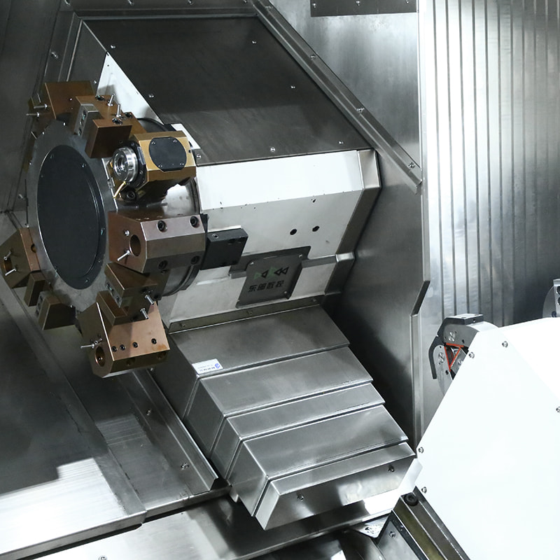
350M series slant lathe integrates 35º stepped bed guide rails (high and low rails), A2-8 high-torque electric spindle, and BMT65 power milling turret, the standard programmable hydraulic center frame, servo tailstock, optional sub-spindle and other functional components have launched a machining solution for slender shafts. Multiple processes such as turning, milling, boring, drilling, tapping, and reaming can be completed in one clamping. It can reduce the number of clampings and improve processing accuracy; shorten the product manufacturing process chain and improve production efficiency.
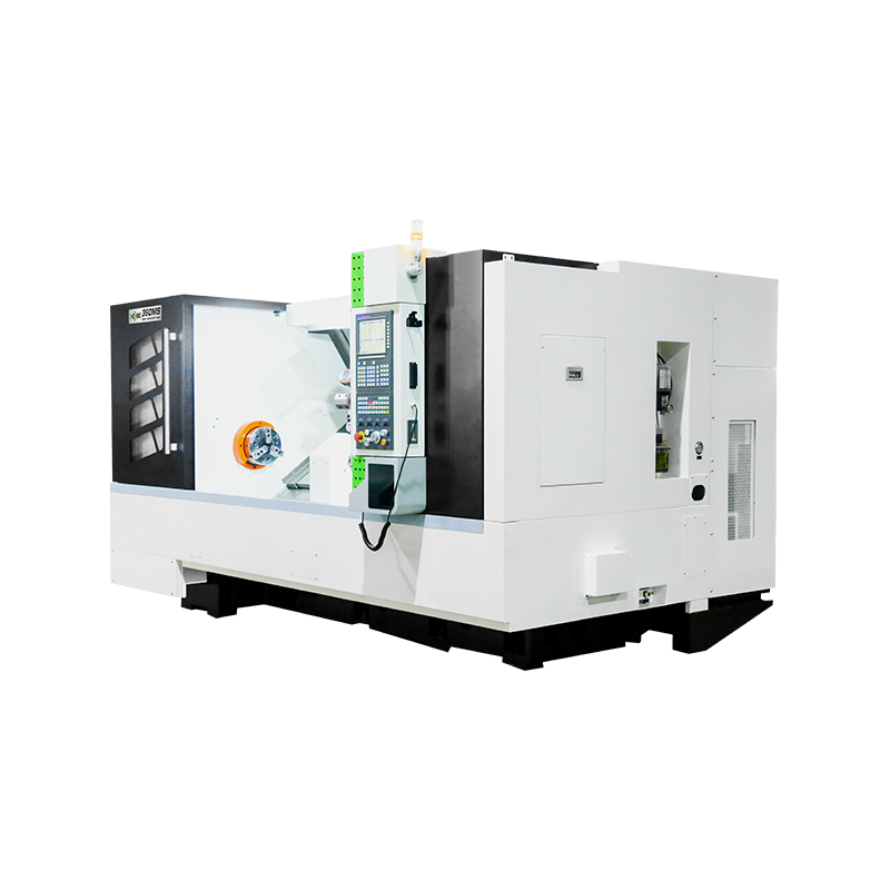
The 350MS turning-milling center is the ideal turning and milling solution for slender shafts. When the ratio of the length of a shaft workpiece to its diameter is greater than 25 (L/d>25), it is called a slender shaft, such as oil cylinders and piston rods, heavy machinery transmission shafts, screws, etc. During the turning process of such slender shaft parts, due to their poor rigidity, the slender shaft is easily bent and deformed under the action of cutting force, own gravity, rotational centrifugal force, and cutting heat, thus destroying the relative relationship between the tool and the part. The interpolation accuracy of the motion causes the processed slender shaft axis to produce wavy flow, which seriously affects the machining accuracy of the part. At the same time, the bending deformation of the slender shaft will also cause vibration in the process system, seriously affecting the roughness of the parts. At present, domestic and foreign manufacturers usually turn and mill slender shaft parts using long-stroke turning and milling composite centers, and use a hydraulic center frame for supporting processing. After the turning process is completed, they are then ground with a grinder.
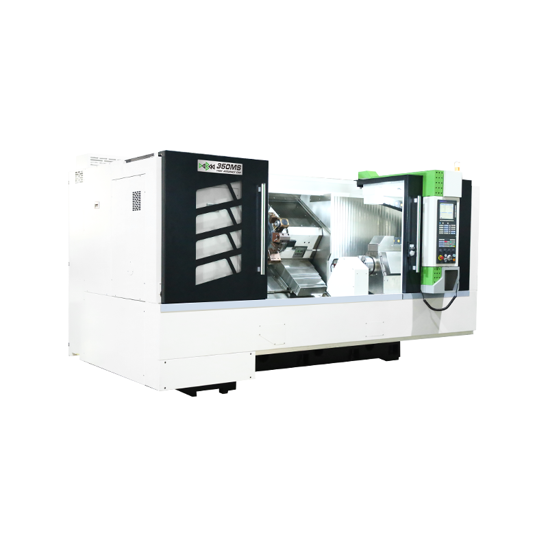
1. The 350 series machine tools integrate the 35° stepped bed guideway, A2-8 high-power spindle, and servo turret or driven tool turret (milling turret).
2. The servo tailstock is standard configuration. Additionally, optional functional components such as a programmable hydraulic steady rest and a sub-spindle are available for machining slender shafts.
3. Multiple processes such as turning, milling, boring, drilling, tapping, and reaming can be completed with a single clamping. This can reduce the number of clamping, improve machining accuracy, shorten the product manufacturing process chain, and increase production efficiency.
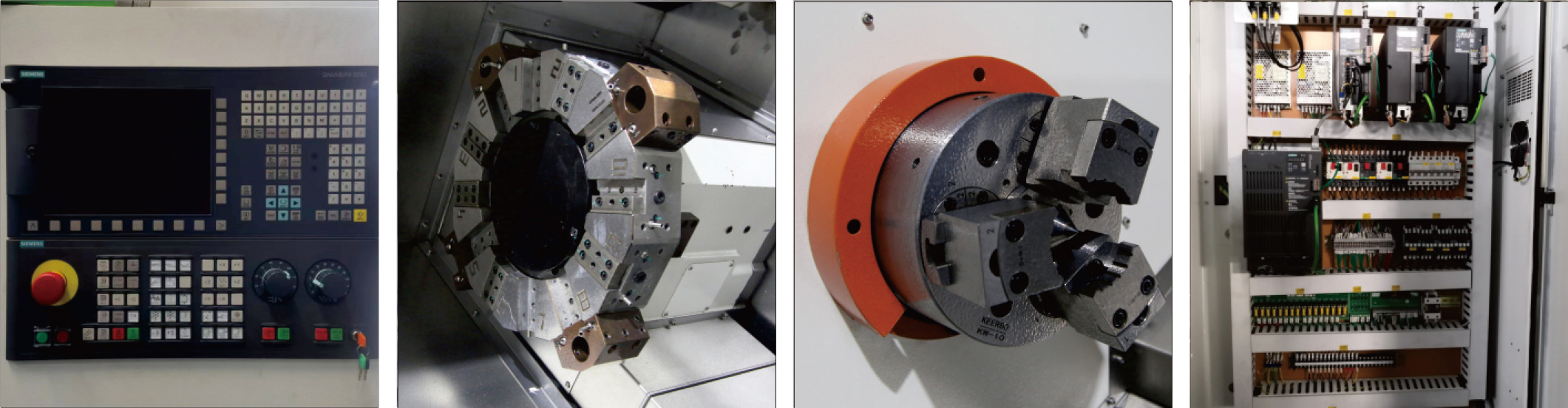
Main Parts of Slant Lathe Machine
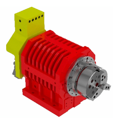 |
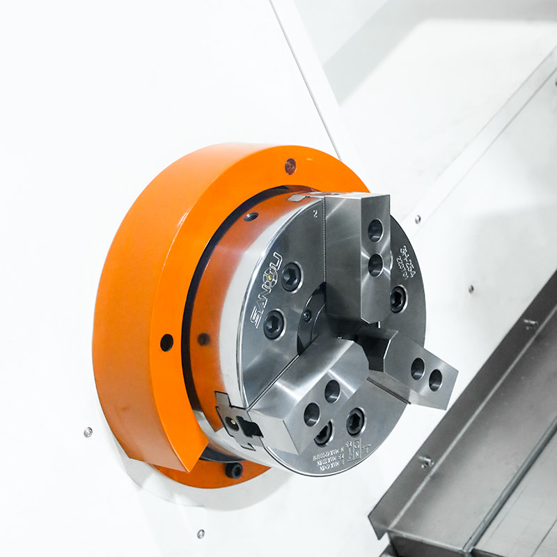
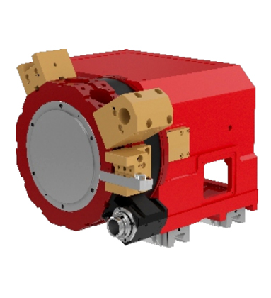
Built-In SpindleThe spindle is driven by a high-torque, high-efficiency, and high-performance permanent magnet synchronous motor. Additionally, P4 double-row short cylindrical roller bearings are adopted. This setup ensures the spindle's high precision, rigidity, and stability. Spindle Speed: 3000rpm Spindle Power: 26.5kW Spindle Taper Hole: Ф86mm |
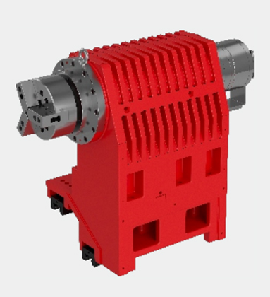
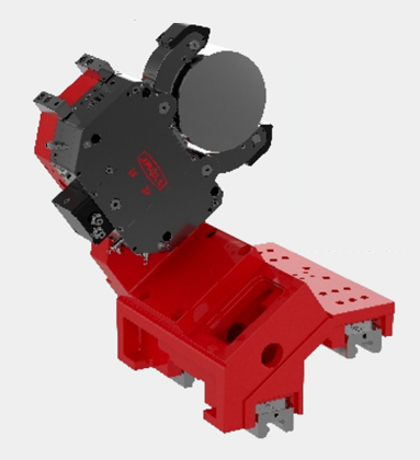
Sub-spindleThe sub-spindle holds and turns a workpiece for it to be machined at the front and back sides. This means one clamping completes all or most of the turning processes, reducing manual intervention and improving the machining efficiency. Sub-spindle Speed: 4000rpm Sub-spindle Power: 22 kW |
 |
 |
Integrated Driven Tool TurretThe driven tool turret is characterized by high positioning accuracy, a compact design, and fast. It enables tool changes without lifting, thereby boosting machining efficiency. |
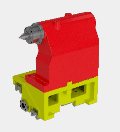
Servo TailstockServo motor control enables a rapid response to control signals, guaranteeing precise adjustment of position and clamping force during machining. This significantly enhances production efficiency and machining precision. |
 |
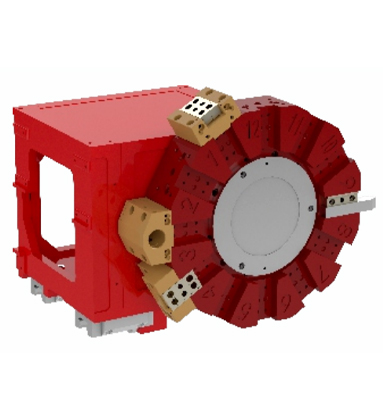 |
Integrated Servo TurretThe turret and the carriage are integrated and directly connected to the linear guideway, making the structure more compact. With the same structural dimensions, a larger end gear disc can be used, increasing rigidity and stability. When indexing and locking, the tool disc does not have a lifting action, which preserves precision, extends lifespan, and boosts the machine tool's machining efficiency. |
Programmable Steady RestCenter frame interpolation is achieved by using an independent and compact screw drive mechanism to pull the center frame slide. |
 |
Slant Lathe 350M Series Features
Adopts 35°Machine Bed, High Rigidity, with the Hydraulic Servo 12 Tool Post Turret, Built-in Spindle, Hydraulic Through Chuck, and Servo Programmable Tailstock, the good choice for Heavy Cutting and Long Shaft Processing.
|
Standard |
Optional |
|
1. SIEMENS 828D Basic Control System |
1. FANUC 0i-TF Plus Control System |
|
2. A2-8 |
2. GSK 988TA Absolute Control System |
|
3. Hydraulic Through Chuck 10inch |
3. RENEISHAW Auto Tool Setter |
|
4. Hydraulic Servo 12 Tool Post Turret |
4. Auto Bar Feeder |
|
5. Servo Programmable Tailstock |
5. Oil Skimmer |
|
6. Hydraulic Steady |
6. Chip Conveyor |
|
7. Roller Linear Guideway |
7. 12 Post Driven Tool Turret (BMT65) |
350M Slant Lathe Specification
| Configuration | 350M | ||
| Machining Capacity | Maximum Swing Over Bed | φ/mm | 720 |
| Maximum Swing Over Slide | φ/mm | 400 | |
| Maximum Machining Length | mm | 1650(If with hydraulic steady,1500mm | |
| Maximum Diameter of Bar | φ/mm | 74 | |
| Maximum Machining Diameter | φ/mm | 400 | |
| Built-in Spindle | Spindle Head Type | GB59001 | A2-8 |
| Spindle Taper Hole | φ/mm | 86 | |
| Spindle Speed Range | rpm | 30-3000 | |
| Spindle Shift Mode | Built-in Spindle | ||
| Spindle Output Torque | N·m | Rated 220 | |
| Spindle Power | kW | 26.5 | |
| Chuck Type | Hydraulic Through Chuck | ||
| Chuck Size | inch | 10" | |
| Feed Rate | Rapid Traverse Speed On X-axis | m/min | 20 |
| Rapid Traverse Speed On Z-axis | m/min | 15 | |
| Rapid Traverse Speed On Z1-axis | m/min | 15 | |
| Servo Motor Torque On X-axis | N·m | 18 | |
| Servo Motor Torque On Z-axis | N·m | 22 | |
| X-axis Travel | mm | 380 | |
| Z-axis Travel | mm | 1650 | |
| Z1-axis Travel | mm | 1600 | |
| Guideway Type | Roller Linear Guideway | ||
| Turret | Turret Type | Hydraulic Servo 12 Tool Post Turret | |
| Tool Size | mm | 25×25/φ40 | |
| Turret Servo Motor Torque | N·m | 9.5 | |
| Tailstock | Tailstock Type | Servo Programmable | |
| Internal Taper of Tailstock Sleeve | MT5 | ||
| Tailstock Travel | mm | 1600 | |
| Power Source | Total Rated Power | KVA | 48 |
| Total Rated Current | A | 100 | |
| Dimension | Machine Weight | kg | 8600 |
| Machine Dimension | L*W*H(mm) | 4000×2100×2300 | |
Please note that there may be slight differences in appearance and parameter depending on your options.
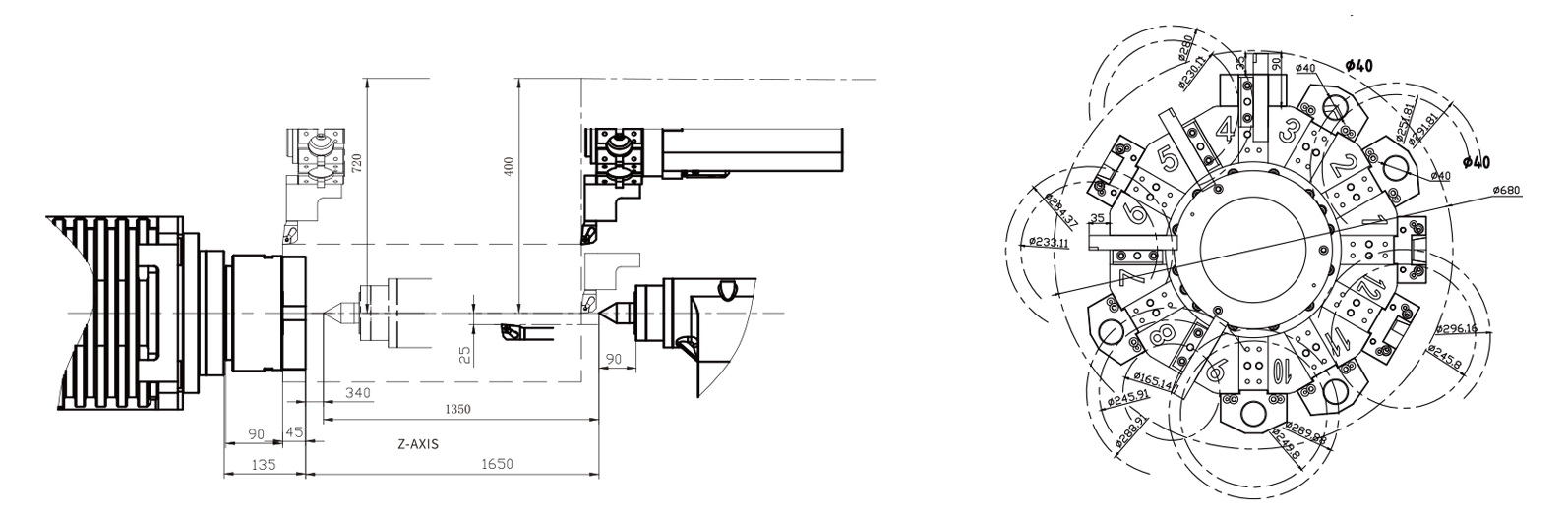
Tool Interferogram
350MS CNC Slant Lathe Specification
| Configuration | 350MS | 350MS With Sub-Spindle | ||
| Machining Capacity | Maximum Swing Over Bed | φ/mm | 720 | 720 |
| Maximum Swing Over Slide | φ/mm | 400 | 400 | |
| Maximum Machining Length | mm | 1540 (If with hydraulic steady,1390mm) |
1540 | |
| Maximum Machining Diameter | φ/mm | 400 | 400 | |
| Maximum Diameter of Bar | φ/mm | 74 | 74 | |
| Built-in Spindle | Spindle Head Type | GB59001 | A2-8 | A2-8,with Sub-Spindle A2-6 |
| Spindle Taper Hole | φ/mm | 86 | 86, with Sub-Spindle 62 | |
| Spindle Speed Range | rpm | 30-3000 | 50-3000, with Sub-Spindle 50-4000 | |
| Spindle Shift Mode | Built-in Spindle | Built-in Spindle | ||
| Spindle Output Torque | N·m | Rated 220 | Rated 220, Max 606 with Sub-Spindle Rated 105, Max 183 |
|
| Spindle Power | kW | 26.5 | 26.5, with Sub-Spindle 22 | |
| Chuck Type | Hydraulic Through Chuck | HydraulicThrough Chuck | ||
| Chuck Size | inch | 10" | 10", with Sub-Spindle Chuck 8" | |
| Feed Rate | Rapid Traverse Speed On X-axis | m/min | 18 | 20 |
| Rapid Traverse Speed On the Z-axis | m/min | 22 | 15 | |
| Rapid Traverse Speed On Z1-axis | m/min | 15 | 15 | |
| Servo Motor Torque On X-axis | N·m | 18 | 18 | |
| Servo Motor Torque On Z-axis | N·m | 22 | 22 | |
| Servo Motor Torque On Z1-axis | N·m | 15 | ||
| X-axis Travel | mm | 320 | 320 | |
| Z-axis Travel | mm | 1540 | 1540 | |
| Z1-axis Travel | mm | 1680 | ||
| Sub-Spindle Travel | mm | 1500 | ||
| Guideway Type | Roller Linear Guideway | |||
| Turret | Turret Type | 12 Post Driven Tool Turret(BMT65) | ||
| Tool Size | mm | 25×25/φ32/ER40 | ||
| Turret Servo Motor Torque | N·m | 9.5 | 9.5 | |
| Driven Tool Servo Motor Torque | N·m | 16.7 | 16.7 | |
| Tailstock | Tailstock Type | Servo Programmable | ||
| Internal Taper of Tailstock Sleeve | MT5 | —— | ||
| Tailstock Travel | mm | 1600 | —— | |
| Power Source | Total Rated Power | KVA | 48 | |
| Total Rated Current | A | 100 | ||
| Dimension | Machine Weight | kg | 8620 | 8720 |
| Machine Dimension | L*W*H(mm) | 4000×2100×2300 | ||
Please note that there may be slight differences in appearance and parameter depending on your options.
350MS-L Slant Lathe Machine Specification
| Configuration | 350M-L | 350MS-L | ||
| Machining Capacity | Maximum Swing Over Bed | φ/mm | 720 | 720 |
| Maximum Swing Over Slide | φ/mm | 400 | 400 | |
| Maximum Machining Length | mm | 2000 | 1890 | |
| Maximum Machining Diameter | φ/mm | 400 | 400 | |
| Maximum Diameter of Bar | φ/mm | 100 | 100 | |
| Built-in Spindle | Spindle Head Type | GB59001 | A2-11 | A2-11 |
| Spindle Taper Hole | φ/mm | 131 | 131 | |
| Spindle Speed Range | rpm | 30-2000 | 30-2000 | |
| Spindle Shift Mode | Built-in Spindle | Built-in Spindle | ||
| Spindle Output Torque | N·m | Rated 320 | Rated 320 | |
| Spindle Power | kW | 36.9 | 36.9 | |
| Chuck Type | Hydraulic Through Chuck | Hydraulic Through Chuck | ||
| Chuck Size | inch | 15" | 15" | |
| Feed Rate | Rapid Traverse Speed On X-axis | m/min | 20 | 20 |
| Rapid Traverse Speed On Z-axis | m/min | 15 | 15 | |
| Rapid Traverse Speed On Z1-axis | m/min | 15 | 15 | |
| Servo Motor Torque On X-axis | N·m | 18 | 18 | |
| Servo Motor Torque On Z-axis | N·m | 22 | 22 | |
| X-axis Travel | mm | 380 | 380 | |
| Z-axis Travel | mm | 2000 | 1890 | |
| Z1-axis Travel | mm | 2030 | 2030 | |
| Guideway Type | Roller Linear Guideway | Roller Linear Guideway | ||
| Turret | Turret Type | Hydraulic Servo 12 Tool Post Turret |
12 Post Driven Tool Turret(BMT65) |
|
| Tool Size | mm | 25×25/φ40 | 25×25/φ32/ER40 | |
| Turret Servo Motor Torque | N·m | 9.5 | 9.5 | |
| Driven Tool Servo Motor Torque | N·m | 16.7 | ||
| Tailstock | Tailstock Type | Servo Programmable | Servo Programmable | |
| Internal Taper of Tailstock Sleeve | MT5 | MT5 | ||
| Tailstock Travel | mm | 2030 | 2030 | |
| Power Source | Total Rated Power | KVA | 48 | 48 |
| Total Rated Current | A | 100 | 100 | |
| Dimension | Machine Weight | kg | 9200 | 9220 |
| Machine Dimension | L*W*H(mm) | 5200×2100×2300 | 5200×2100×2300 | |
Please note that there may be slight differences in appearance and parameter depending on your options.
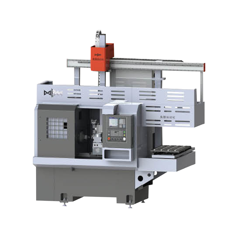
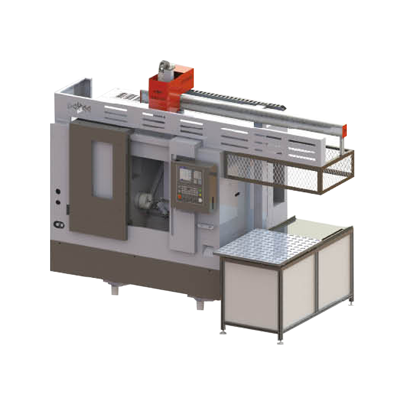
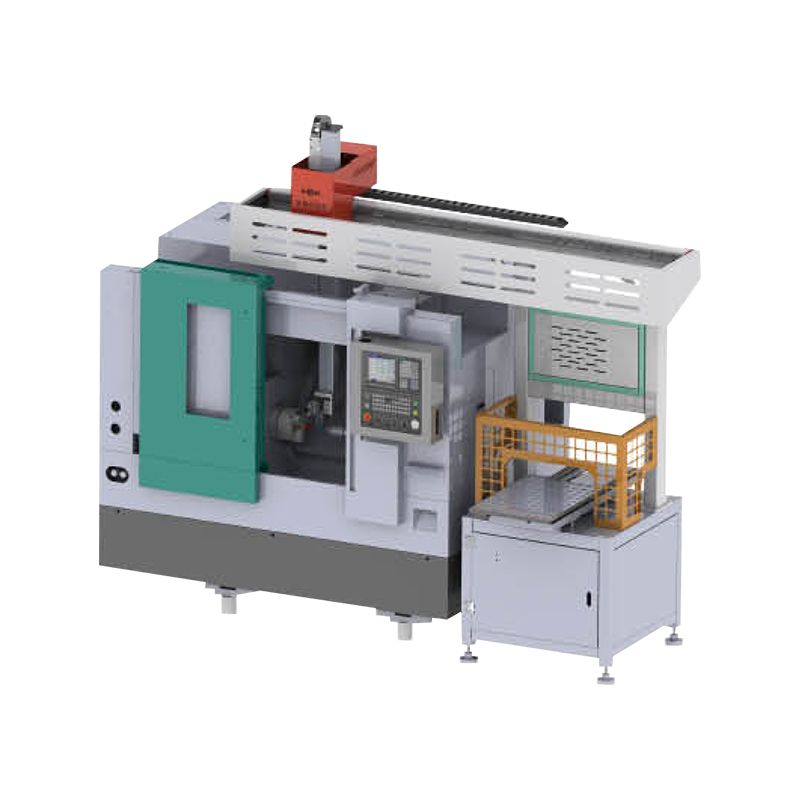
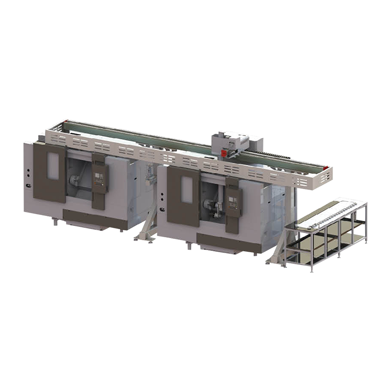
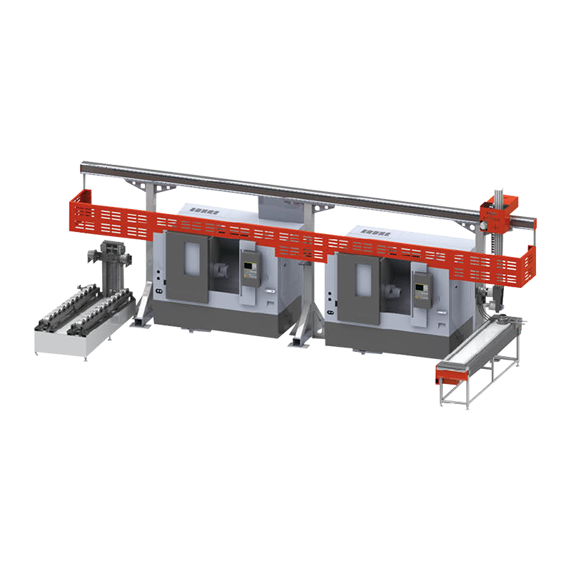
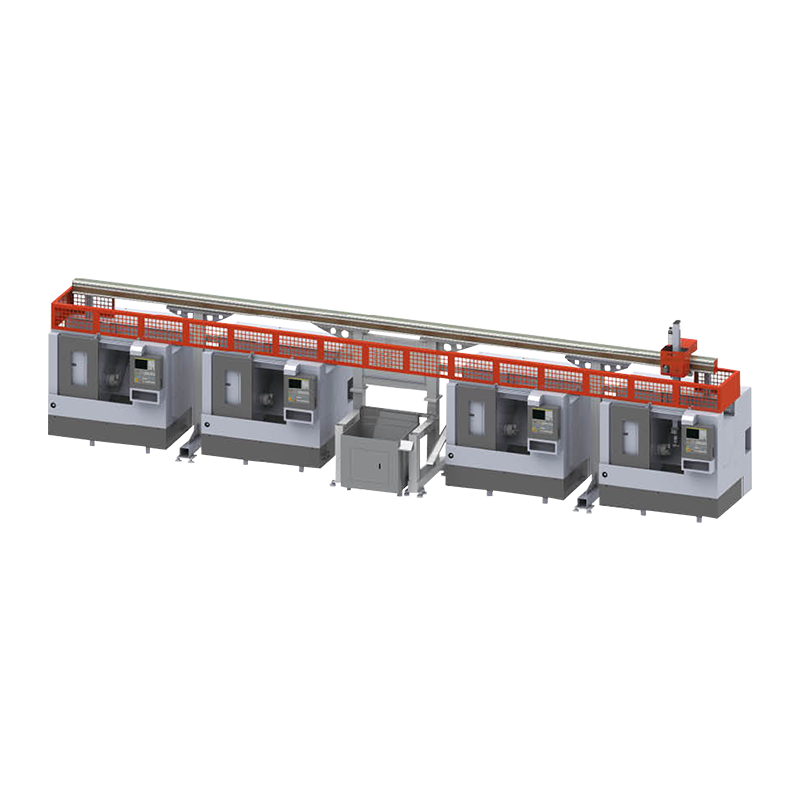
350M Series Slant Lathe Application
Frequently Asked Questions
Q1: What is the primary application of the 350M / 350M-L / 350MS series?
The 350M series is a slant-bed CNC lathe equipped with a sub-spindle, designed specifically to enable the complete machining of long shaft-type parts and complex turn-mill components within a single machine cycle. By integrating a main spindle, a synchronized sub-spindle, and a live tool turret, the 350M series eliminates the need for manual re-chucking to machine the opposite end of a part; the sub-spindle automatically retrieves the part from the main spindle, completes the machining of the reverse side, and ejects the finished part—all automatically executed within a single, uninterrupted program cycle.
Q2: What are the differences between the 350M, 350M-L, and 350MS models?
The 350M is the standard platform model, integrating sub-spindle functionality with live tooling to enable complete turn-mill machining. The 350M-L features an extended Z-axis travel and an increased distance between the two spindles to accommodate long shaft-type workpieces that are too long to be fully machined within the travel range of the standard model. The 350MS is additionally equipped with a steady rest or an enhanced tailstock support system, specifically dedicated to machining exceptionally long or slender shaft-type parts; such parts require intermediate support during the machining process to prevent deflection and ensure dimensional accuracy.
Q3: How does the sub-spindle work on the 350M series?
The sub-spindle on the 350M series is a fully powered spindle, synchronized with the CNC system, and mounted on the Z-axis opposite the main spindle. Once the main spindle has completed all machining operations on the first end of the workpiece, the sub-spindle advances—under the control of the CNC system—to clamp the finished end, after which the main spindle releases the workpiece. Subsequently, the sub-spindle retracts to its machining position; at this point, the main spindle turret—or the second turret, if a dual-turret system is installed—performs turning and milling operations on the end of the workpiece that was previously unclamped. Finally, the fully machined part is automatically ejected or conveyed via a chute.
Q4: What types of parts are best suited for machining on the 350M Series?
The 350M Series is ideally suited for machining complex shaft-type parts—particularly those requiring machining operations at both ends and along their entire length—such as drive shafts, pump shafts, spindles, medical bone screws, automotive fastener assemblies, and precision pin assemblies. For any workpiece that previously required two separate lathe setups—or manual part re-chucking—to complete machining on both ends, the sub-spindle capability of the 350M Series offers an excellent solution.
Q5: Does the 350M Series support Y-axis milling capabilities?
Whether or not a specific 350M Series machine possesses Y-axis milling capabilities depends on the specific configuration ordered. The Y-axis function enables eccentric milling, keyway cutting, and the milling of complex contours positioned eccentrically relative to the main spindle centerline—operations that cannot be performed solely using the C-axis and live tooling. If your part family includes features requiring eccentric milling or flat-bottomed slotting, please be sure to confirm with the manufacturer whether the specific machine model you are considering is equipped with the Y-axis function.
Q6: What is the maximum shaft length that can be accommodated by the 350M-L model?
The 350M-L model is specifically designed for long shaft-type workpieces, aiming to extend the turning length capacity beyond that of the standard 350M model. The specific maximum shaft length limit is determined by the Z-axis travel range configured for the machine, as well as the distance between the face of the main spindle and the face of the sub-spindle. When verifying this technical parameter, you should use the longest workpiece in your production schedule as the benchmark for comparison; additionally, you must account for any overhang created by the bar feeder, as well as any residual length of the workpiece that may protrude outward after being fully clamped by the sub-spindle.
Q7: What type of CNC control system does the 350M Series utilize to simultaneously manage the main spindle, sub-spindle, and live tooling?
The 350M Series machines require a multi-channel CNC control system to enable the synchronized management of the main spindle, sub-spindle, turret, and live tooling. Currently, the primary control systems available as options include the FANUC 0i-TF series, featuring a dual-path configuration, and the Siemens 840D SL series, which offers multi-channel control capabilities. Both of these major control platforms support main/sub-spindle synchronization (facilitating automatic workpiece transfer), dual-spindle C-axis control, synchronized operation of live tools, and a "balanced cutting" mode—a feature designed to maximize machining cycle efficiency through simultaneous processing by both the main and sub-spindles.
Q8: Compared to using a standard lathe, what improvements in production efficiency can be expected after switching to the 350M series machine tools?
Transitioning from a standard single-spindle lathe to the 350M series typically yields significant gains in production efficiency: it eliminates the need for manual re-chucking operations (saving anywhere from 3 to 10 minutes per workpiece, depending on its weight and complexity); it obviates the setup requirements for a second machine tool; and it reduces positioning errors caused by re-chucking (errors that can compromise the concentricity between the two ends of a workpiece). Furthermore, this machine series integrates turning and milling operations—which would otherwise require two separate machine tools to complete—into a single, unified machining cycle. For the high-volume production of shaft-type workpieces, the cumulative effect of these various efficiencies translates into substantial optimizations regarding unit production costs, labor requirements, and workshop floor space utilization.
KEEP IN TOUCH
About Us
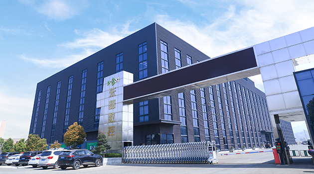
Taizhou Eastern CNC Technology Co., Ltd.
We are a well-known brand and professional wholesale 350M/350M-L/350MS/350MS With Sub-Spindle Slant Lathe for Long Shaft Turning and Milling in China. It is committed to providing professional machine tools and production application solutions to global users, and actively provides customization. It has more than 650 employees. With different models and more than 40 derivative products, we strive to achieve the vision goal of "building a famous brand in the machine tool equipment manufacturing industry".
Certificate Of Honor


News
-
Overview In the metal-cutting industry, the "machine bed" is a component often overlooked by buyers, yet it is the decisive factor in whether a lathe can operate with long-term stability. While the v...
READ MORE -
Introduction In the past two years, many small and medium-sized machine shops have faced a common set of challenges: difficulty in recruiting skilled labor, shrinking batch sizes, and increasingly co...
READ MORE -
Overview Talk to anyone who's actually run a metalworking lathe for a living, and one thing comes up again and again: get the machine wrong, and every step after that gets harder. A shaft that's only...
READ MORE -
Abstract Double-turret CNC lathes and dual-spindle CNC lathes are two machine tool configurations frequently discussed together in the field of precision parts manufacturing. While both aim to boost ...
READ MORE -
Abstract As the demand for precision manufacturing continues to evolve, Y-axis lathes are increasingly becoming a focal point for manufacturing enterprises. Compared to traditional CNC lathes, Y-axis...
READ MORE
How to buy CNC machine tools
-
01
Contact Us
All of your quotes will be answered within 2 hours by our professional sales support.
-
02
Get A Free Quote
Use reliable parts and components to ensure product quality.
-
03
Fast Delivery
You can expect your order fulfilled within 60 days after placing the order.
-
04
After-sale Support
All our products come with a one-year warranty.
-

-

sales@east-cnc.com
-

Shangma Industry Area, Shitang Town, Wenling City, Taizhou, Zhejiang, China.
-

Products
Message
Copyright © Taizhou Eastern CNC Technology Co., Ltd.

Machine Tool Manufacturer Privacy Policy