


 English
 русский
 Español
 عربى
عربى 简体中文
简体中文
Contact Us
All of your quotes will be answered within 2 hours by our professional sales support.
Industry News
 Home / News / Industry News / Detailed Guide to CNC Turning Processes: Operations, Tooling, and Applications
  2026.04.17
 Industry News
Contents
CNC (Computer Numerical Control) lathe machining stands as one of the core processes in modern manufacturing, utilizing programmed, precise control of tool paths to achieve high-precision cutting and shaping of materials such as metals and plastics. A complete CNC lathe machining workflow encompasses several critical stages, each of which directly impacts the precision and quality of the final component.
Drawing Analysis → Process Planning → Program Generation → Tool Preparation → Workpiece Setup → Tool Setting → Rough Machining → Finish Machining → Inspection & Warehousing
The workholding stage serves as the foundation of the entire workflow; the workpiece is typically positioned and secured using fixtures such as three-jaw self-centering chucks, four-jaw independent chucks, or centers and steady rests. This ensures that the workpiece remains free from displacement or vibration throughout the machining process. Workholding precision directly determines the datum accuracy for all subsequent operations; therefore, the operator must carefully calibrate for runout, with radial runout error generally required to be within 0.01 mm.
Once the tool setting and programming are complete, the machine executes the operations—sequencing through rough turning, semi-finish turning, and finish turning—in accordance with pre-set G-code instructions. By progressively reducing the cutting depth and feed rate, the process ultimately achieves the dimensional tolerances, geometric tolerances, and surface finish requirements specified in the engineering drawings.
CNC lathes are capable of executing a wide range of fundamental cutting processes, thereby meeting the shaping requirements for the majority of parts with rotational symmetry:
Removes excess material from the end face of the workpiece, establishes an axial datum, and ensures flatness.
Machines cylindrical surfaces and enables precise diameter control; this constitutes the more fundamental turning operation.
Creates through-holes or blind holes along the workpiece's centerline, often followed by fine-finishing using a boring tool.
Precisely enlarges existing holes, thereby enhancing hole diameter accuracy and the surface quality of the internal bore.
Machines external or internal surfaces with a standard taper, typically for applications requiring mating fits.
Utilizes contour programming to machine complex profile features, such as curved surfaces and arcs.
| Machining Process | Rough Turning | Finish Turning |
| Cutting Depth | 1.5–5 mm | 0.05–0.5 mm |
| Feed Rate | 0.2–0.6 mm/rev | 0.05–0.15 mm/rev |
| Cutting Speed | Lower | Higher |
| Primary Objective | Rapid removal of large amounts of excess material | Ensuring dimensional accuracy and surface quality |
| Tolerance Requirements | IT12–IT14 | IT6–IT8 |
| Coolant | High-flow forced cooling | Precision spray or oil mist cooling |
In actual production, a semi-finish turning operation is often interposed between these two stages; a machining allowance of 0.3–0.5 mm is left behind to serve as a transition prior to finish turning. This step further eliminates internal stress deformation induced by rough turning, thereby ensuring dimensional stability during the subsequent finish turning process.
Thread turning is one of the more representative feature machining processes performed on CNC lathes. By precisely synchronizing the spindle encoder with the feed axis, a linked control is achieved wherein the feed rate per revolution is strictly equal to the thread pitch. CNC systems support specialized commands—such as G32 (thread cutting) and G76 (compound threading cycle)—enabling the machining of various thread types, including metric, imperial, pipe threads, and tapered threads. Typical thread accuracy can reach the 6g/6H tolerance class, with a surface roughness of Ra ≤ 1.6 μm.
The grooving process is used to machine annular channels such as relief grooves, sealing grooves, and O-ring grooves. The width of the grooving tool must match the required groove width; during cutting, a low feed rate (0.03–0.08 mm/rev) is required to prevent tool breakage. For wide grooves, a combined approach is typically employed, involving multiple radial depth cuts followed by a lateral pass to complete the feature.
The cut-off process serves as the final operation in the mass production of parts from bar stock; it involves feeding a cut-off tool radially inward toward the workpiece's centerline to separate the finished part from the bar stock. During the cut-off process, a steady supply of cutting fluid must be maintained to prevent the tool tip from chipping or fracturing due to the accumulation of cutting heat.
As manufacturing demands have diversified, modern CNC lathes have evolved beyond traditional 2-axis configurations to encompass a variety of advanced machine models, significantly expanding the machining capabilities of a single machine tool.
By adding a linear Y-axis motion capability to the standard C-axis (spindle orientation control), the lathe gains the ability to machine eccentric holes, keyways, and flat surfaces. Powered tools are mounted in the turret, enabling combined turning and milling operations without the need for secondary fixturing, thereby significantly reducing errors associated with transferring the workpiece between operations.
Equipped with both a front and a rear spindle, these machines automatically transfer a part from the front spindle—where front-side machining is completed—to the sub-spindle for back-side machining, eliminating the need for manual flipping or re-chucking. This configuration is particularly well-suited for complex shaft-type and disc-type parts requiring machining on both ends, resulting in a cycle time reduction of over 40%.
By integrating both a turning spindle and a milling spindle (featuring a pivoting B-axis), this process enables the completion of all operations—ranging from external turning to five-sided milling—within a single workpiece setup. It is ideally suited for complex-shaped components in the aerospace, medical, and mold-making industries; by eliminating the cumulative errors associated with multiple setups, it achieves an overall precision level of IT5.
The judicious selection of cutting tools is critical to ensuring machining quality, enhancing efficiency, and reducing costs. Tool selection requires a comprehensive assessment of various factors, including workpiece material, machining operations, machine tool power, and cooling methods.
| Tool Type | Material | Applicable Operations | Recommended Materials |
| External Turning Tools (CNMG/WNMG) | Coated Carbide | Rough Turning, Finish Turning | Steel, Cast Iron, Stainless Steel |
| Boring Bars (S-Type Shank) | Ultra-Fine Grain Carbide | Internal Boring, Finish Boring | Steel, Aluminum, Cast Iron |
| Thread Turning Tools (60°/55°) | PVD-Coated Carbide | Threading | Steel, Stainless Steel, Titanium Alloys |
| Grooving Tools (2mm/3mm/4mm) | Carbide | Grooving, Cut-off | All Metal Materials |
| Ceramic Inserts | Silicon Nitride / SiAlON Ceramic | High-Speed Finish Turning | Hardened Steel, Cast Iron (HRC 40+) |
| CBN Inserts | Cubic Boron Nitride | Hard Turning (Turning-as-Grinding) | Hardened Steel (HRC 60+) |
| PCD Diamond Inserts | Polycrystalline Diamond | Ultra-Precision Finishing | Aluminum Alloys, Copper, Composite Materials |
Tool Selection Principles: For machining standard carbon steel, P-class (blue) coated inserts are the preferred choice; for stainless steel, select M-class (yellow); for cast iron, select K-class (red). When machining difficult-to-cut materials (such as titanium alloys or superalloys), prioritize the use of specialized tool holders equipped with internal coolant channels; this directs the cutting fluid directly to the tool tip, effectively reducing cutting temperatures by over 50%.
Crankshafts, camshafts, piston pins, brake discs, etc. These parts demand high production throughput and exceptional consistency; production lines featuring dual spindles and automated loading/unloading systems are widely employed, with tolerance requirements typically falling within ±0.005 mm.
Transmission shafts, lead screws, spindles, and other slender shafts. These require support from a steady rest or follower rest to prevent machining vibrations, and a segmented turning strategy is utilized to maintain coaxiality.
Hydraulic cylinder bodies, valve blocks, and piston rods. The sealing surfaces of internal bores require a surface roughness of Ra ≤ 0.4 μm, typically necessitating a process of precision boring followed by lapping; external chrome-plated surfaces utilize a combined process of precision turning and grinding.
Flanges, end caps, gear rings, etc. These parts require clamping on both the front and back sides, with a critical focus on controlling face runout and parallelism. Dual-spindle lathes enable the complete machining of both sides in a single loading operation.
Aluminum alloy wheel hubs demand a simultaneous focus on lightweight design and high precision. Machining is performed via high-speed turning (1200–2500 rpm) utilizing PCD inserts; the internal bore and face are machined in a single clamping setup to ensure a runout tolerance of ≤ 0.1 mm.
In the realm of CNC lathe manufacturing and technical services, support from specialized enterprises serves as a vital guarantee for elevating the standard of machining processes.
A technology-driven enterprise dedicated to the field of CNC lathes, providing one-stop solutions ranging from equipment selection and process consulting to tooling integration. With extensive industry experience spanning diverse manufacturing sectors—including automotive and hydraulics—the company empowers businesses to achieve their goals of high-efficiency, precision machining.
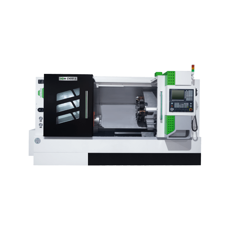
RECOMMENDED PRODUCTS
All of your quotes will be answered within 2 hours by our professional sales support.
Use reliable parts and components to ensure product quality.
You can expect your order fulfilled within 60 days after placing the order.
All our products come with a one-year warranty.



sales@east-cnc.com

Shangma Industry Area, Shitang Town, Wenling City, Taizhou, Zhejiang, China.

Copyright © Taizhou Eastern CNC Technology Co., Ltd.

Machine Tool Manufacturer Privacy Policy