


 English
 русский
 Español
 عربى
عربى 简体中文
简体中文
Contact Us
All of your quotes will be answered within 2 hours by our professional sales support.
Industry News
 Home / News / Industry News / Does the chip removal design of a vertical turning center affect machining efficiency?
  2026.07.24
 Industry News
Contents
Spindle power. Chuck diameter. Travel range. These are the numbers everyone reaches for when specing out a vertical turning center — understandably so, given what these machines are now expected to handle. Large-diameter, heavy-duty parts have become the norm rather than the exception: flanges, bearing housings scaled up for industrial use, hubs built for wind turbines. Tables on these machines regularly exceed a meter in diameter, and a workpiece can run anywhere from a couple hundred kilograms up into multi-ton territory.
There's a detail that gets missed in almost every one of these conversations, and it's chip removal. Not glamorous. Easy to treat as background noise. But get it wrong, and the fallout isn't subtle — surfaces come out rougher than spec, tools dull ahead of schedule, and the machine ends up stopping more than it runs. Auxiliary feature? Maybe on paper. In the shop, it's often the one thing standing between a machine that just keeps cutting and one that keeps needing attention.
In horizontal lathe machining, the workpiece is positioned horizontally and the tool cuts from the side; chips fall naturally due to gravity into the chip removal trough beneath the machine bed, following a relatively direct path.
Vertical turning centers operate differently. The workpiece sits flat on the table, and the tool cuts from above. Once generated, a significant portion of the chips falls directly onto the table surface or around the chuck, or even becomes lodged in the gaps between the workpiece and the fixture. In this case, gravity offers little help; chips do not simply "slide away" on their own but tend to accumulate on the rotating table, spinning along with the workpiece.
This structural difference means that vertical turning centers rely much more heavily on effective chip removal design; one cannot simply replicate the approaches used for horizontal lathes.
Chip accumulation on the worktable is not merely an eyesore; it triggers a chain reaction of issues:
While these issues may seem minor in isolation, their cumulative effect is greatly amplified in a continuous production environment.
Different manufacturers employ various chip evacuation strategies for vertical turning centers; common methods include:
Some machine models feature guards with sloped inner walls combined with flow-directing structures at the worktable edge. This allows chips to slide toward a designated outlet, driven by a combination of centrifugal force and gravity. This design works good with fragmented or short chips; long, stringy chips tend to snag on corners.
These are two common mechanical chip evacuation solutions. Screw-type conveyors use a rotating auger to push chips forward and are suitable for handling small, granular, or fragmented chips. Hinged-belt conveyors offer higher load-bearing capacity and can handle larger, heavier chips, making them ideal for heavy-duty cutting of cast iron or steel components. The choice between the two depends primarily on the workpiece material and the volume of chips generated.
Mechanical systems alone may not always ensure complete chip removal; using coolant flushing as a supplementary measure is a common practice. High-pressure internal cooling delivers coolant directly to the cutting zone through internal tool channels; this simultaneously lowers the temperature and flushes out chips, making it particularly useful for deep-hole machining and for materials that do not break into chips easily.
This detail is easily overlooked but has a significant impact. If the chip outlet position and the table rotation direction are not properly coordinated, chips may be "flung" in the wrong direction, accumulating instead in hard-to-clean corners inside the machine. A well-designed system ensures a smooth alignment between the chip trajectory and the chip outlet.
The table below summarizes the application scenarios for several mainstream chip removal methods:
| Chip Removal Method | Chip Form | Common Materials | Key Advantages |
| Tilted Table/Guard | Fragmented/short chips | Cast iron, brittle materials | Simple structure, low maintenance cost |
| Spiral Chip Conveyor | Fragmented/granular chips | Cast iron, aluminum alloys | Continuous transport, compact footprint |
| Hinged-Belt Conveyor | Long strips/blocky chips | Steel parts, heavy-duty cutting | High load-bearing capacity |
| High-Pressure Internal Cooling | Curled/sticky chips | Stainless steel, ductile materials | Combines cooling and chip flushing |
Chip forms vary greatly depending on the material, so the chip removal system must be selected accordingly.
When machining cast iron, chips are usually fragmented and detach easily, placing fewer demands on the conveyor system's continuous transport capabilities. When machining steel—especially medium-to-high carbon steel—chips often form long strips or coils; without a chip-breaking mechanism, they tend to tangle, making a combination of a hinged-belt conveyor and a chip-breaking tool insert more practical. Aluminum alloy chips are relatively soft and prone to sticking to the tool; high-pressure coolant flushing is often required to prevent chips from adhering to the workpiece surface and compromising machining accuracy.
In other words, if a customer frequently changes the materials machined on the same piece of equipment, the adaptability of the chip removal system becomes a critical factor to evaluate, as a single-function chip removal design may not be sufficient for diverse operating conditions.
In high-volume continuous production, chip removal efficiency directly impacts the frequency of manual intervention.
In mass production scenarios, machine tools are designed to operate for extended periods with little to no human supervision. If chip removal efficiency is inadequate, operators must frequently intervene to clear chips, disrupting the production rhythm. Conversely, a well-designed chip removal system minimizes manual intervention, allowing actual uptime to approach theoretical capacity; the impact on overall productivity is cumulative, meaning the performance gap widens over time.
Key parameters and structural details to consider during procurement:
When selecting a machine, beyond standard specifications like spindle power and travel range, it is advisable to clarify the following points:
While these details may seem minor, they are critical factors determining whether the equipment can operate stably over the long term.
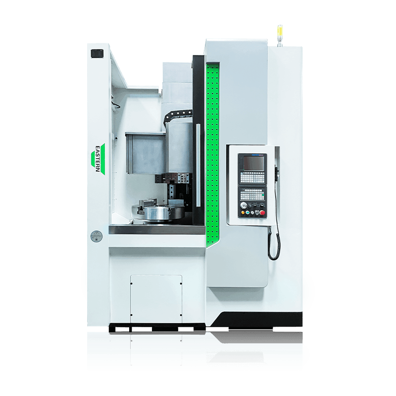
Horizontal lathes rely on gravity for natural chip discharge along a relatively direct path. In contrast, vertical turning centers feature a flat-mounted workpiece and top-down cutting; chips tend to accumulate around the table and chuck, necessitating specific structural designs to guide them out of the machine.
Yes, it does. Chip accumulation can cause secondary scratching on the workpiece surface or accelerate tool wear due to heat concentration, thereby compromising dimensional stability—an effect that is particularly pronounced during prolonged, continuous machining.
Cast iron produces fragmented chips that are relatively easy to handle; steel tends to produce long, continuous chips, requiring effective chip-breaking strategies; aluminum alloy chips are soft and prone to adhering to the tool, usually necessitating high-pressure coolant to assist with evacuation. The choice of chip evacuation system should be based on the primary materials being machined.
Yes. Chip accumulation often leads to heat concentration in the cutting zone, accelerating tool wear; furthermore, if chips become entangled with the tool, they can directly damage the cutting edge and shorten the tool's service life.
You can assess factors such as the type of chip conveyor, the alignment between the chip discharge outlet and the table's rotation direction, and the availability of high-pressure internal coolant capabilities. Additionally, consider the primary materials you will be machining and consult the manufacturer to ensure the chip evacuation solution is specifically tailored to your needs.
RECOMMENDED PRODUCTS
All of your quotes will be answered within 2 hours by our professional sales support.
Use reliable parts and components to ensure product quality.
You can expect your order fulfilled within 60 days after placing the order.
All our products come with a one-year warranty.



sales@east-cnc.com

Shangma Industry Area, Shitang Town, Wenling City, Taizhou, Zhejiang, China.

Copyright © Taizhou Eastern CNC Technology Co., Ltd.

Machine Tool Manufacturer Privacy Policy