200MSY/200MSY With Sub-Spindle Y-Axis CNC Slant Bed Lathe Supplier


200MSY/200MSY With Sub-Spindle Y-Axis CNC Slant Bed Lathe
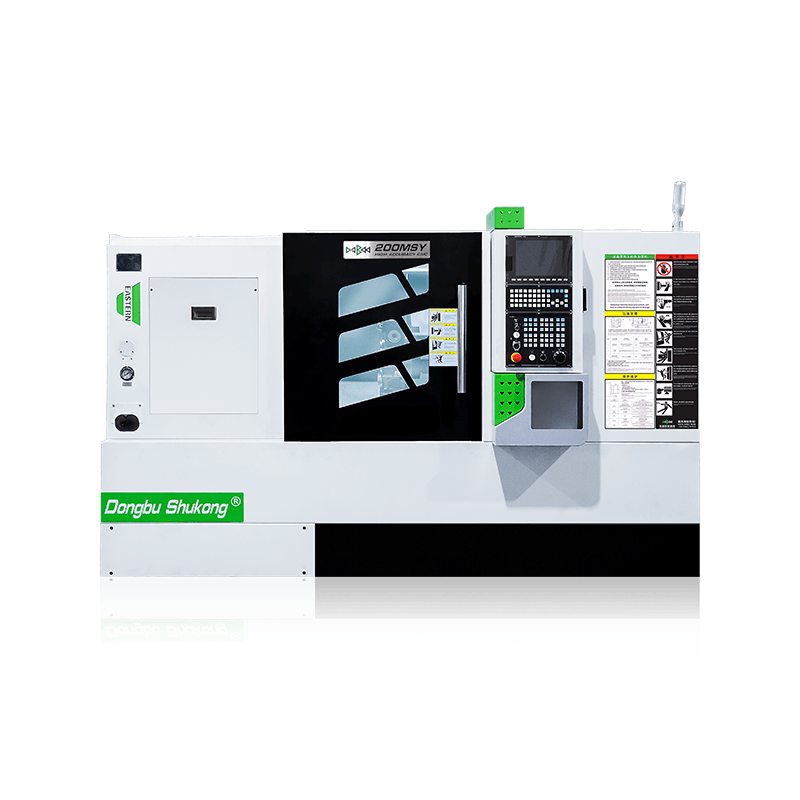
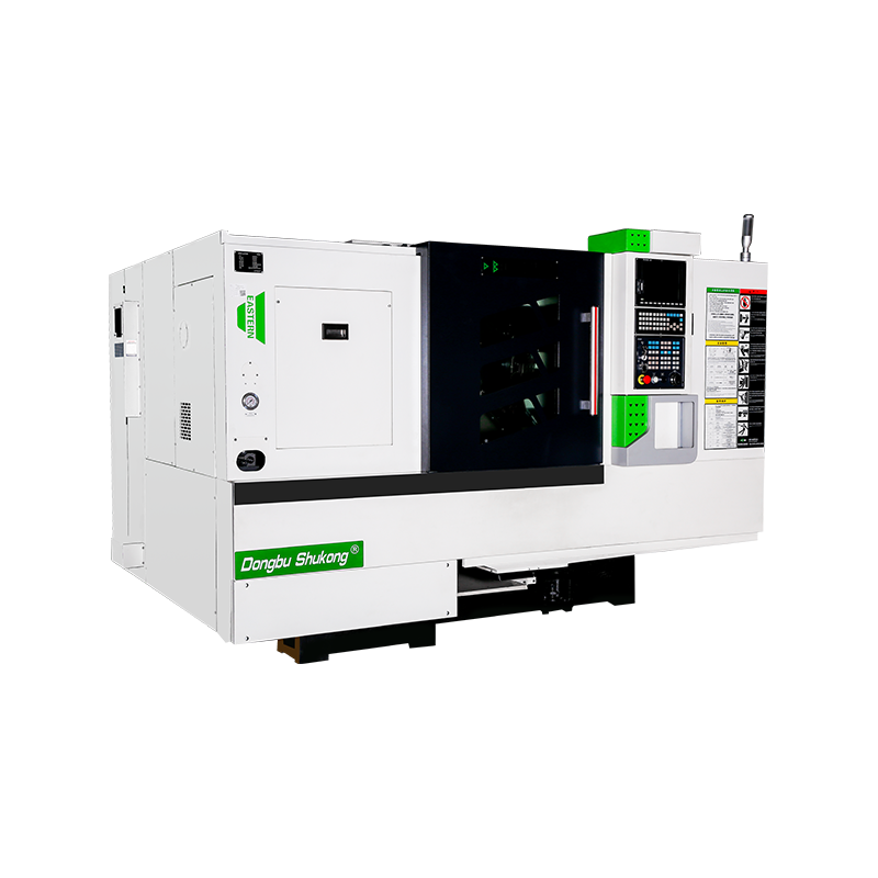
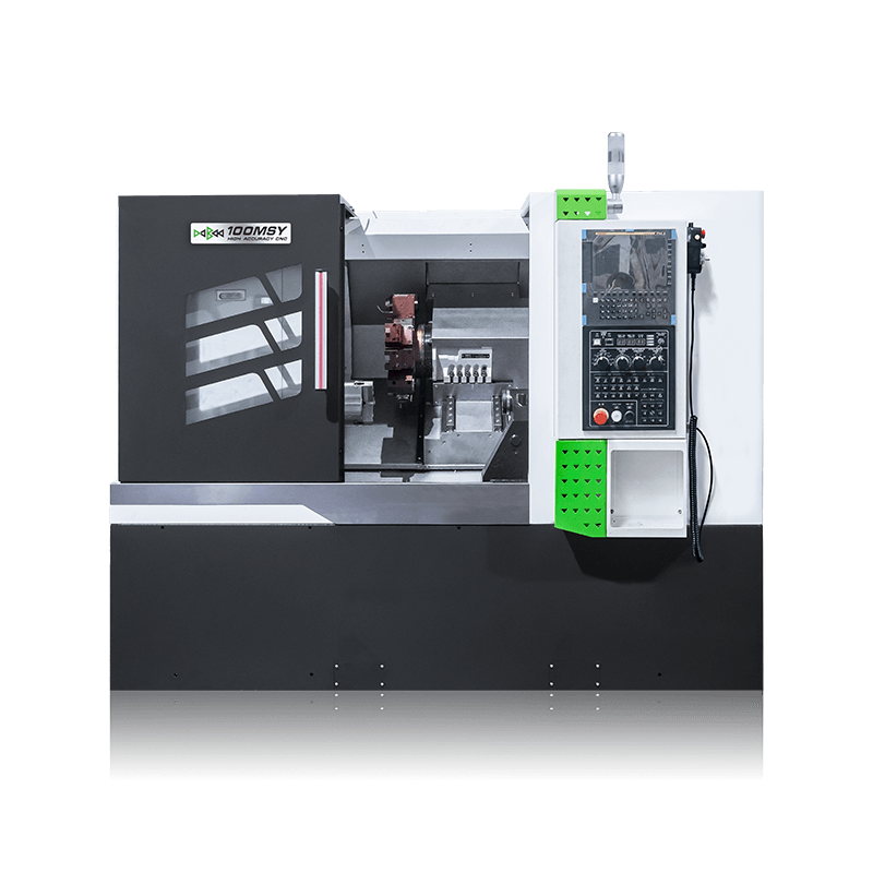
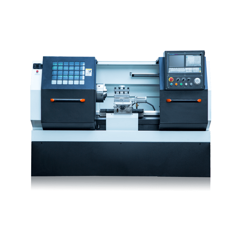
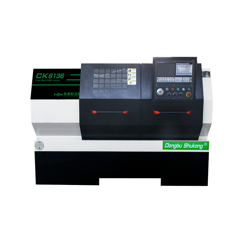
The milling functionality of the 200MSY interpolation Y-axis turning and milling composite center is achieved through an L-type high-rigidity bed, equipped with a 35° inclined high-rigidity interpolation Y-axis, an A2-8 type 220/606 N·m high-precision high-torque permanent magnet synchronous spindle, and a BMT55 type integrated tray-type high-rigidity power tool turret. Standard features include a programmable servo tailstock, with optional components such as the A2-5 sub-spindle, offering a process solution tailored for high-rigidity Y-axis turning and milling composite operations. It can perform various machining processes such as internal and external cylindrical surfaces, steps, grooves, conical surfaces, arc surfaces, end faces, and chamfers on various shaft-type and disc-type parts with a single setup, and can also machine various standard threads.
1. L-shaped bed structure
2. Permanent magnet synchronous electric spindle
3. High rigidity interpolation axis structure
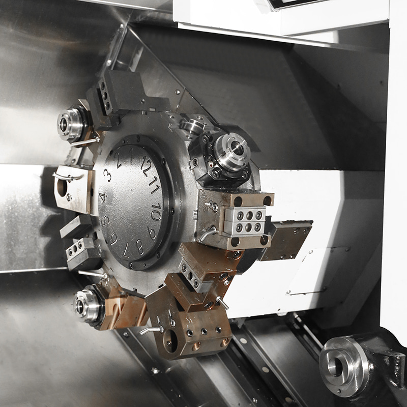
4. High rigidity integrated power tool turret
|
|
Maximum Machining Diameter: 360mm |
 |
Maximum Machining Length: 560mm |
 |
Chuck Size: 8" inch |

-
DETAIL PARAMETERS
-
VIDEO DISPLAY
200MSY CNC Slant Bed Lathe Introduction
The function of 200MSY/200MSY With Sub-Spindle CNC Slant Bed Lathe With Y-Axis is realized by a flat bed equipped with a 35º oblique interpolation Y-axis and a power milling turret. Multiple processes such as turning, milling, boring, drilling, tapping, and reaming can be completed in one clamping. It can reduce the number of clampings, improve processing accuracy, shorten the product manufacturing process chain, and improve production efficiency.
1. The high-rigidity Y-axis is realized through the movement of the middle (inclined) and large (horizontal) slides, which involves continuous two-axis interpolation. This enables milling operations with maximum rigidity.
2. The driven tool turret integrates the slide and utilizes a high-precision three-piece contrate-gear clutch. This ensures high positioning accuracy, excellent repeatability, and strong clamping rigidity.
3. The high-rigidity spindle employs both liquid and air cooling methods for motor heat dissipation. This approach guarantees the spindle's service life and machining precision.
4. The programmable tailstock is equipped with overload protection and is driven by a servo motor for movement and clamping. This significantly improves machining efficiency.
Description of the basic structural features of the Lathe machine tool
1. Bed
L-shaped high-rigidity bed structure made of high-grade inoculated cast iron. Through FEM finite element structural analysis, the casting interior incorporates a large number of reinforcing ribs, optimizing the internal load-bearing structure of the entire machine and ensuring its rigidity and thermal field stability.
2. High-rigidity interpolation Y-axis structure
The upper and lower slides form a 35° inclined Y-axis structure, achieving high-rigidity Y-axis characteristics. The Y-axis is realized through the X-axis and a Y1-axis with a certain angle relative to the X-axis. The upper and lower bed saddles form a virtual Y-axis structure by interpolation on the high and low bed frames, with the Y-coordinate perpendicular to the X-coordinate. When the Y-coordinate moves, the X-axis and Y1-axis move simultaneously. This structure effectively overcomes the shortcomings of direct Y-axis structures, enhancing machine tool rigidity, particularly during heavy-duty turning operations (no tool holder overhang on the Y-axis). Another feature of this structure is its rational machine layout, compact footprint,and high cost-effectiveness.
3. Integrated Tray-Type High-Rigidity Power Tool Turret
The power tool turret is integrated with the lathe's tray and directly connected to the guideway. Compared to the traditional structure where the turret is a separate functional component connected to the tray, this design is more compact. Under the same structural dimensions, it can use a larger end gear disk, thereby achieving higher rigidity and better stability.
The power module is housed within the tool turret tray and directly connected to the drive servo motor, eliminating intermediate synchronous belts or other transmission chains, resulting in agile and high-precision transmission.
The power module is housed within the tool turret's tool disk and directly connected to the drive servo motor, eliminating intermediate synchronous belts and other transmission chains, resulting in agile and high-precision transmission. The servo motor drives the gears for tool selection and indexing, hydraulic release and locking, and high-precision three-piece end-tooth clutch positioning. The high-durability non-separable design ensures excellent positioning accuracy, repeatability, and clamping rigidity.
4. High-precision, high-torque permanent magnet synchronous spindle
Based on permanent magnet synchronous motor theory, the high-rigidity, high-torque synchronous spindle has a rated output torque of 220 N·m, maximum output torque 606 N·m, and maximum speed 3,000 RPM.
The permanent magnet synchronous spindle eliminates the traditional belt structure, improving the machine tool's response speed and enhancing processing efficiency;
the machine tool adopts a direct-coupled structure, improving processing accuracy to meet high-speed precision machining requirements;
it addresses the issue of insufficient low-speed high-torque rough turning force in machine tools.
5. High-rigidity roller guideways
Roller guides feature high rigidity, high load-bearing capacity, and high precision, making them particularly suitable for high-load, high-speed applications.
Compared to ball guides, roller guides have more contact points, allowing for even load distribution and reduced relative friction during movement, resulting in high precision and high repeatability.
Roller guides have a long service life and can be used in high-load, harsh environments for extended periods, thereby reducing the frequency and cost of replacement and maintenance. Maintenance of roller guide rails is relatively simple; during use, only proper lubrication according to specifications is required.
6. Programmable Tailstock
Programmable tailstocks offer advantages such as high automation, high precision, strong flexibility, wide applicability, and convenient maintenance, making them suitable for processing rotating workpieces that require high precision and repeatability.
The adjustment and positioning of the programmable tailstock can be controlled through programming, ensuring precision and repeatability. Driven by servo motors and ball screws, the tailstock generates consistent clamping force.
Through system programming, the thrust in the Z-axis direction of the tailstock can be adjusted to meet the corresponding clamping force requirements of materials in different processing environments.
It provides support for long and heavy workpieces to achieve consistent high-precision turning processing.
7. Optional Sub-Spindle
The 200MSY-type interpolation Y-axis turning and milling composite center can be equipped with a permanent magnet synchronous sub-spindle with a rated output torque of
37 N·m, a maximum output torque of 130 N·m, and a maximum speed of 3,500 RPM. It enables operations such as single-setup turning and face turning.
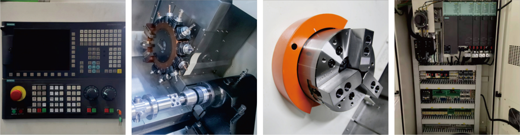
Main Parts of Slant Bed Lathe
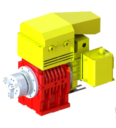 |
Built-In SpindleThe spindle is driven by a high-torque, high-efficiency, and high-performance permanent magnet synchronous motor. Additionally, P4 double-row short cylindrical roller bearings are adopted. This setup ensures the spindle's high precision, rigidity, and stability. Spindle Speed: 4000rpm Spindle Power: 18.5 kW Spindle Taper Hole: Φ62 Mm |
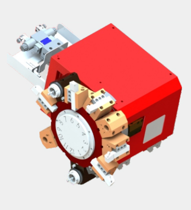
Integrated Driven Tool TurretThe driven tool turret is characterized by high positioning accuracy, a compact design, and fast. It enables tool changes without lifting, thereby boosting machining efficiency. |
 |
200MSY CNC Slant Bed Lathe Features
Adopts 35°Machine Bed, High Rigidity Y-Axis with 12 Post Driven Tool Turret BMT55, with Built-in Spindle (max spindle speed 4000rpm), Hydraulic Through Chuck, and Servo Programmable Tailstock, Extremly Shorten the Working Time for Shaft and Plate Workpiece Processing.
|
Standard |
Optional |
|
1. SIEMENS 828D Basic Control System |
1. FANUC 0i-TF Plus Control System |
|
2. A2-6 |
2. SYNTEC 22TB Control System |
|
3. Built-in Spindle |
3. GSK 988TA Absolute Control System |
|
4. Hydraulic Through Chuck 8inch |
4. RENEISHAW Auto Tool Setter |
|
5. 12 Post Driven Tool Turret (BMT55) |
5. Auto Bar Feeder |
|
6. Servo Programmable Tailstock |
6. Oil Skimmer |
|
7. Roller Linear Guideway |
7. Chip Conveyor |
200MSY CNC Slant Bed Lathe Specification
| Configuration | 200MSY | 200MSY With Sub-Spindle | ||
| Machining Capacity | Maximum Swing Over Bed | φ/mm | 560 | 560 |
| Maximum Swing Over Slide | φ/mm | 300 | 300 | |
| Maximum Machining Length | mm | 560/800 | 560 | |
| Maximum Diameter of Bar | φ/mm | 52 | 52 | |
| Maximum Machining Diameter | φ/mm | 350 | 350 | |
| Built-in Spindle | Spindle Head Type | GB59001 | A2-6 | A2-6,with Sub-Spindle A2-5 |
| Spindle Taper Hole | φ/mm | 62 | 62, with Sub-Spindle 55 | |
| Spindle Speed Range | rpm | 50-4000 | 50-4000, with Sub-Spindle 50-5000 | |
| Spindle Shift Mode | Built-in Spindle | Built-in Spindle | ||
| Spindle Output Torque | N·m | 180 | Rated155/Max286,with Sub-Spindle Rated37/Max113 | |
| Spindle Power | kW | 22 | 22, with Sub-Spindle 10.8 | |
| Chuck Type | Hydraulic Through Chuck | Hydraulic Through Chuck | ||
| Chuck Size | inch | 8" | 8",with Sub-SpindleChuck 6" | |
| Feed Rate | Rapid Traverse Speed On X-axis | m/min | 30 | 30 |
| Rapid Traverse Speed On Y-axis | m/min | 10 | 10 | |
| Rapid Traverse Speed On Z-axis | m/min | 30 | 30 | |
| Rapid Traverse Speed On Z1-axis | m/min | 25 | —— | |
| Servo Motor Torque On X-axis | N·m | 16.7 | 16.7 | |
| Servo Motor Torque On Y-axis | N·m | 16.7 | 16.7 | |
| Servo Motor Torque On Z-axis | N·m | 16.7 | 16.7 | |
| Sub-Spindle Servo Motor Torque | N·m | —— | 8.34 | |
| Servo Motor Torque On Z1-axis | N·m | 8.9 | —— | |
| X-axis Travel | mm | 180 | 180 | |
| Y-axis Travel | mm | +60 -40 | +60 -40 | |
| Z-axis Travel | mm | 570/810 | 560 | |
| Sub-Spindle Travel | mm | 500 | ||
| Z1-axis Travel | mm | 620/860 | —— | |
| Guideway Type | Roller Linear Guideway | |||
| Turret | Turret Type | 12 Post Driven Tool Turret(BMT55) | ||
| Tool Size | mm | 25×25/φ40/ER32 | ||
| Tailstock | Tailstock Type | Servo Programmable | —— | |
| Internal Taper of Tailstock Sleeve | MT5 | |||
| Tailstock Travel | mm | 620/860 | ||
| Power Source | Total Rated Power | KVA | 43 | |
| Total Rated Current | A | 95 | ||
| Dimension | Machine Weight | kg | 4500/4820 | 4800 |
| Machine Dimension | L*W*H(mm) | 2790X1900X1940/ 3030X1900X1940 |
2790×1900×1940 | |
| Configuration | 200MSY(A2-8) | 200MSY(A2-8)With Sub-Spindle | ||
| Machining Capacity | Maximum Swing Over Bed | φ/mm | 560 | 560 |
| Maximum Swing Over Slide | φ/mm | 300 | 300 | |
| Maximum Machining Length | mm | 500 | 500 | |
| Maximum Diameter of Bar | φ/mm | 85 | 85 | |
| Maximum Machining Diameter | φ/mm | 350 | —— | |
| Built-in Spindle | Spindle Head Type | GB59001 | A2-8 | A2-8,with Sub-Spindle A2-5 |
| Spindle Taper Hole | φ/mm | 86 | 86, with Sub-Spindle 55 | |
| Spindle Speed Range | rpm | 50-3000 | 50-3000, with Sub-Spindle 50-3500 | |
| Spindle Shift Mode | Built-in Spindle | Built-in Spindle | ||
| Spindle Output Torque | N·m | Rate220 Max606 | Rated 200/Max606,with Sub-Spindle Rated37/Max113 | |
| Spindle Power | kW | 26.5 | 26.5, with Sub-Spindle 10.8 | |
| Chuck Type | Hydraulic Through Chuck | Hydraulic Through Chuck | ||
| Chuck Size | inch | 10" | 10",with Sub-SpindleChuck 6" | |
| Feed Rate | Rapid Traverse Speed On X-axis | m/min | 30 | 30 |
| Rapid Traverse Speed On Y-axis | m/min | 10 | 10 | |
| Rapid Traverse Speed On Z-axis | m/min | 30 | 30 | |
| Rapid Traverse Speed On Z1-axis | m/min | 20 | —— | |
| Servo Motor Torque On X-axis | N·m | 16.7 | 16.7 | |
| Servo Motor Torque On Y-axis | N·m | 16.7 | 16.7 | |
| Servo Motor Torque On Z-axis | N·m | 16.7 | 16.7 | |
| Sub-Spindle Servo Motor Torque | N·m | —— | 8.34 | |
| Servo Motor Torque On Z1-axis | N·m | 8.9 | —— | |
| X-axis Travel | mm | 180 | 180 | |
| Y-axis Travel | mm | +60 -40 | +60 -40 | |
| Z-axis Travel | mm | 500 | 500 | |
| Sub-Spindle Travel | mm | 650 | ||
| Z1-axis Travel | mm | 620 | ||
| Guideway Type | Roller Linear Guideway | Roller Linear Guideway | ||
| Turret | Turret Type | 12 Post Driven Tool Turret(BMT55) | 12 Post Driven Tool Turret(BMT55) | |
| Tool Size | mm | 25×25/φ40/ER32 | 25×25/φ40/ER32 | |
| Tailstock | Tailstock Type | Servo Programmable | ||
| Internal Taper of Tailstock Sleeve | MT5 | —— | ||
| Tailstock Travel | mm | 620 | —— | |
| Power Source | Total Rated Power | KVA | 43 | 43 |
| Total Rated Current | A | 95 | 95 | |
| Dimension | Machine Weight | kg | 4800 | 5100 |
| Machine Dimension | L*W*H(mm) | 2790X1900X1940 | 2790×1900×1940 | |
Please note that there may be slight differences in appearance and parameter depending on your options.
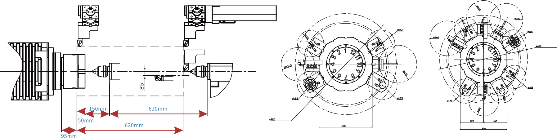
Tool Interferogram
200MSY Slant Bed CNC Lathe Application
Frequently Asked Questions
Q1: What makes the 200MSY different from a standard CNC slant bed lathe?
The 200MSY combines four advanced machining capabilities into a single platform: a high-precision slant bed turning configuration, a synchronized sub-spindle for complete part machining in one cycle, live tooling for powered milling and drilling operations, and a Y-axis that enables true off-centre milling at positions eccentric to the spindle centreline. This combination transforms the machine from a standard turning centre into a complete turn-mill machining cell capable of producing highly complex, multi-feature components without any intermediate workpiece handling or re-fixturing between operations.
Q2: What is the Y-axis, and why is it important on the 200MSY?
The Y-axis is a linear axis perpendicular to both the spindle axis (Z) and the cross-slide axis (X). While C-axis and live tooling enable milling at radial positions around the spindle centreline, the Y-axis adds the ability to offset the cutting tool laterally from the centreline — enabling true off-centre pocket milling, flat-bottom keyway cutting, eccentric bore machining, and complex multi-plane contour milling that would be impossible or geometrically incorrect without a Y-axis. For complex precision parts with off-centreline features, the Y-axis is the critical differentiator that eliminates the need for a machining centre as a secondary operation.
Q3: How does the sub-spindle work on the 200MSY?
The 200MSY's sub-spindle is a fully synchronized, CNC-controlled second spindle mounted on the Z-axis opposite the main spindle. After the main spindle completes all first-end operations — turning, milling, drilling, and threading — the sub-spindle advances and grips the finished end of the workpiece under precise CNC position and speed synchronization. The main spindle releases, and the sub-spindle retracts to the second-end machining position where the turret completes all reverse-side operations. The fully finished part is then automatically ejected, achieving complete machining in a single uninterrupted cycle.
Q4: What part types are best suited to the 200MSY?
The 200MSY is best suited to medium-diameter, high-complexity parts that require turning, milling, drilling, tapping, and off-centre features on both ends — all in a single setup. Typical applications include complex automotive transmission components, hydraulic valve blocks with cross-drilled passages, medical implant components with complex surface geometries, aerospace actuator parts with multiple feature planes, and high-precision connector bodies requiring tight positional tolerances between features on opposite ends.
Q5: What CNC control system does the 200MSY use?
The 200MSY requires a multi-axis, multi-channel CNC control to coordinate the main spindle (with C-axis), sub-spindle (with C-axis), Y-axis, and live tooling turret simultaneously. FANUC 0i-TF Plus with dual-channel and Y-axis support, and Siemens 840D sl with multi-channel configuration, are the standard control options. Both platforms provide full support for synchronised spindle hand-off, balanced turning, Y-axis milling cycles, and tool life management across all active tool positions.
Q6: What is the turning diameter and bar capacity of the 200MSY?
The 200MSY is configured for medium-diameter workpieces, with turning diameter capacity aligned to the '200' designation in the model name. Bar capacity through the main spindle bore enables bar-fed automatic production of smaller-diameter complex parts. Exact figures for maximum turning diameter, maximum turning length, and spindle bore diameter should be confirmed from the manufacturer's specification sheet for the specific machine configuration being evaluated.
Q7: Can the 200MSY run unattended for extended production periods?
Yes. The 200MSY is designed for high levels of production autonomy. With a bar feeder connected to the main spindle, the machine can continuously produce fully machined, complete parts — turned, milled, drilled, and tapped on both ends — from raw bar stock to finished component without operator intervention between parts. Automatic tool life monitoring, in-process gauging options, and automatic part ejection to a conveyor or chute further extend unattended run capability.
Q8: How does the 200MSY reduce total cost per part compared to multi-machine routing?
The 200MSY eliminates multiple cost drivers present in traditional multi-machine routing: there is no manual part transfer between turning and milling operations, no re-fixturing that introduces positional errors, no queue time between machines, and no separate machine depreciation and labour cost for secondary milling operations. Setup time is reduced to a single programme and tooling set rather than separate setups on a lathe and a machining centre. For complex parts previously requiring three or four separate operations across different machines, the 200MSY can deliver total cycle time reductions of 40–60% alongside measurable improvements in inter-feature positional accuracy.
KEEP IN TOUCH
About Us
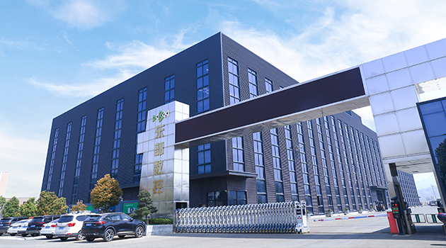
Taizhou Eastern CNC Technology Co., Ltd.
We are a well-known brand and professional wholesale 200MSY/200MSY With Sub-Spindle Y-Axis CNC Slant Bed Lathe in China. It is committed to providing professional machine tools and production application solutions to global users, and actively provides customization. It has more than 650 employees. With different models and more than 40 derivative products, we strive to achieve the vision goal of "building a famous brand in the machine tool equipment manufacturing industry".
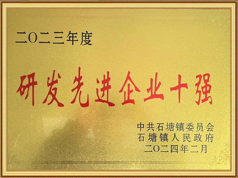
Certificate Of Honor


News
-
Abstract Double-turret CNC lathes and dual-spindle CNC lathes are two machine tool configurations frequently discussed together in the field of precision parts manufacturing. While both aim to boost ...
READ MORE -
Abstract As the demand for precision manufacturing continues to evolve, Y-axis lathes are increasingly becoming a focal point for manufacturing enterprises. Compared to traditional CNC lathes, Y-axis...
READ MORE -
In April 2026, the 14th China CNC Machine Tool Exhibition (CCMT2026) concluded successfully in Shanghai. The event brought together numerous renowned domestic and international enterprises in the CNC...
READ MORE -
What is a Sub-Spindle CNC Lathe? A Sub Spindle Lathe is an advanced version of a standard CNC lathe that incorporates an additional sub-spindle capable of independent rotation and programming. Once t...
READ MORE -
Manufacturing products are becoming increasingly "challenging to produce"—part geometries are growing more complex, times are shrinking, and tolerances are becoming tighter. Faced with this pressure,...
READ MORE
How to buy CNC machine tools
-
01
Contact Us
All of your quotes will be answered within 2 hours by our professional sales support.
-
02
Get A Free Quote
Use reliable parts and components to ensure product quality.
-
03
Fast Delivery
You can expect your order fulfilled within 60 days after placing the order.
-
04
After-sale Support
All our products come with a one-year warranty.
-

-

-

Shangma Industry Area, Shitang Town, Wenling City, Taizhou, Zhejiang, China.
-

Products
Message
Copyright © Taizhou Eastern CNC Technology Co., Ltd.

Machine Tool Manufacturer Privacy Policy