


 English
 русский
 Español
 عربى
عربى 简体中文
简体中文
Contact Us
All of your quotes will be answered within 2 hours by our professional sales support.
Industry News
 2026.01.09
 Industry News
Contents
1. What is "True Y"?
True Y (Real Y) refers to a machine tool that possesses a real, independent Y-axis structure.
Its core characteristics include:
In simple terms:
True Y is like a "real road," where the cutting tool can move freely back and forth along this road.
2. What is "Interpolated Y"?
Interpolated Y is not an independently existing physical axis, but is "calculated" by the CNC system.
Its principle is:
In simple terms:
Interpolated Y is more like simulating forward movement by constantly "turning corners" in the absence of a road; it looks like a Y-axis, but it doesn't actually exist.
3. Comparison Table of True Y and Interpolated Y
| Comparison Item | True Y-axis | Interpolated Y |
| Is it an independent physical axis? | Yes | No |
| Driving method | Independent servo drive | Multi-axis linkage interpolation |
| Rigidity and stability | High | Relatively low |
| Machining accuracy | High | Affected by interpolation accuracy |
| Machinable shapes | Complex side milling, eccentric, irregular shapes | Simple contours |
| Cost | Higher | Lower |
1. Definition of the Z-axis
Determination method:
2. Definition of the X-axis
3. Definition of the Y-axis
4. How to understand multiple Z-axes such as Z1 and Z2?
5. Definition of Rotary Axes (Five-axis/Compound Machining)
The Y-axis not only determines whether the machine can complete compound processes such as side milling and eccentric machining, but its accuracy and stability directly affect the final quality of the part. If the Y-axis is not properly calibrated, even if the tools and program are completely correct, dimensional drift or positional errors may occur.
Direct Impact of Y-axis Accuracy on Machining Quality
Y-axis accuracy is mainly reflected in the following key machining indicators:
The perpendicular relationship between the Y-axis and the X/Z axes determines whether the side milling plane remains at 90° to the reference axis. If there is a slight tilt, the side milling surface will show taper or surface shape errors.
Eccentric machining relies on the accurate displacement of the Y-axis. Any zero-point deviation or backlash will hole position deviation, directly affecting assembly accuracy.
When multiple processes are completed in a single clamping, the Y-axis needs to move back and forth frequently. Its repeatability determines the consistency and batch stability of the machining.
Common Calibration and Adjustment Items for the Y-axis
In practical machine tool maintenance and precision restoration, common calibration and adjustment items include:
This usually involves using precision square rulers, dial indicators, or laser measuring equipment to ensure that the three axes satisfy the orthogonal relationship of the right-hand Cartesian coordinate system.
By resetting the reference point and mechanical zero position, systematic errors caused by zero point drift are avoided.
The backlash generated during the reciprocating movement of the Y-axis is corrected through CNC system compensation parameters to improve positioning consistency.
This includes parameters such as acceleration/deceleration curves, interpolation cycles, and servo gain, ensuring smooth and responsive Y-axis movement.
A Y-axis lathe, by introducing Y-axis motion capabilities, enables traditional turning equipment to perform milling and multi-axis linkage machining functions.
The example part is a stepped shaft, which, in addition to conventional outer diameter and end face machining, requires the following features:
If traditional processes were used, these features would usually require multiple clamping operations, while a Y-axis lathe can complete them in a single clamping operation.
Detailed Machining Process
The workpiece is clamped in the spindle chuck, and end face and outer diameter turning are completed using the Z-axis and X-axis to establish a unified machining datum.
The spindle is switched to C-axis control mode to precisely control the workpiece rotation angle, providing an angular datum for side milling and eccentric machining.
The tool feeds along the Z-axis, and the Y-axis provides lateral offset to complete the side milling of the plane. The direct Y-axis structure provides higher rigidity and surface quality in this process.
By setting the offset amount of the Y-axis and coordinating with the C-axis angle positioning, eccentric holes or eccentric grooves are machined, avoiding errors caused by secondary clamping.
After completing all features, finishing is performed, and key dimensions are verified using an in-machine probe or online measurement function.
Finding the correct centerline on a Y-axis lathe is a prerequisite for ensuring the accuracy of side milling, eccentric holes, and multi-process machining. If the Y-axis centerline is offset, it will directly dimensional asymmetry, magnified positional errors, and even assembly problems. Therefore, this step is crucial before machining.
Common Centerline Finding and Calibration Methods
This is the more widely used and lowest-cost method. By installing a dial indicator on the tool turret or tool holder, the Y-axis is moved equally in both positive and negative directions to check if the indicator returns to zero, thus determining whether the Y-axis center is consistent with the spindle center. This method is suitable for daily calibration and quick checks.
A symmetrical structure (such as left and right symmetrical planes or double-sided grooves) is machined on the workpiece. The center position is verified by measuring whether the dimensions after machining are consistent. This method is intuitive and practical, but it consumes more material and is suitable for the process verification stage.
This is mainly used for high-end or precision Y-axis lathes. This method can comprehensively test the Y-axis positioning accuracy, repeatability, and linearity, and is suitable for machine tool installation and commissioning or annual accuracy verification.
In conjunction with the in-machine probe system, the program automatically collects data and calculates the center deviation, achieving fast and repeatable automatic calibration. This is suitable for mass production environments.
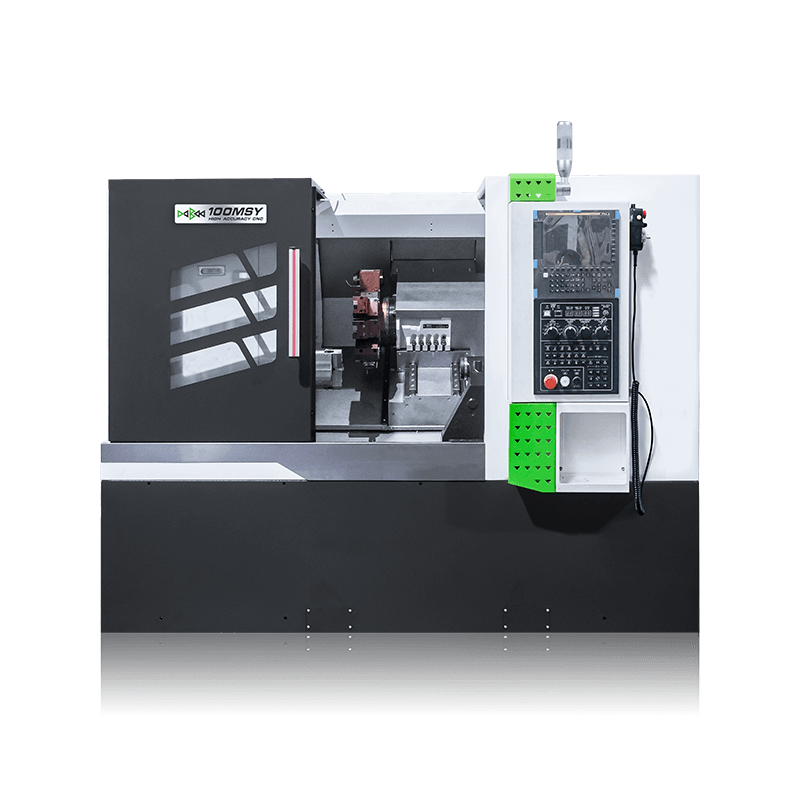
100MSY – Small to Medium-sized Integrated Y-axis Lathe
Core Advantages
Typical Parameters
Recommended for:
Suitable for machining small to medium-sized complex shafts and disc-shaped parts, such as automotive parts, pump shafts, and accessory parts; production lines with moderate budgets and limited space.
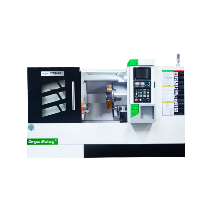
200MSY – Versatile Y-axis Turning and Milling Machining Center
Core Advantages
Typical Parameters
Recommended for
Suitable for medium-sized complex workpieces requiring integrated turning and milling, such as large shafts, rotors, couplings, and flanges; suitable for medium to high-capacity production lines.
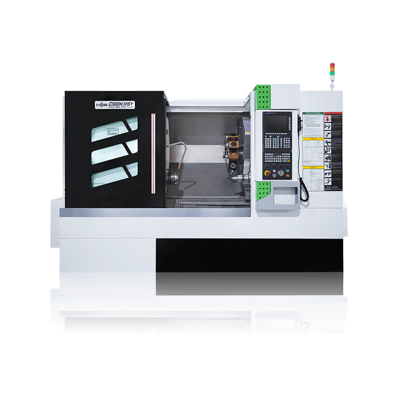
C500K MSY – Heavy-duty Y-axis Slant Bed Lathe
Core Advantages
Typical Parameters
Reasons for Recommendation
Heavy cutting, large size, complex hole and groove machining, and deep processing requirements, such as engineering machinery parts, large disc/shaft parts, and heavy-duty components.
Selection Reference Suggestions
Selection based on workpiece size and complexity
Selection based on automation and production efficiency
Selection based on capacity and future expansion
The three models have different focuses
RECOMMENDED PRODUCTS
All of your quotes will be answered within 2 hours by our professional sales support.
Use reliable parts and components to ensure product quality.
You can expect your order fulfilled within 60 days after placing the order.
All our products come with a one-year warranty.



sales@east-cnc.com

Shangma Industry Area, Shitang Town, Wenling City, Taizhou, Zhejiang, China.

Copyright © Taizhou Eastern CNC Technology Co., Ltd.

Machine Tool Manufacturer Privacy Policy